audi Workshop Repair Guides

Audi Workshop Service and Repair Manuals

Checking electronic engine power control (electronic throttle) > < Checking fuel tank breather
Motronic Fuel Injection and Ignition System (6-cylinder)
Checking fuel tank breather
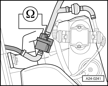
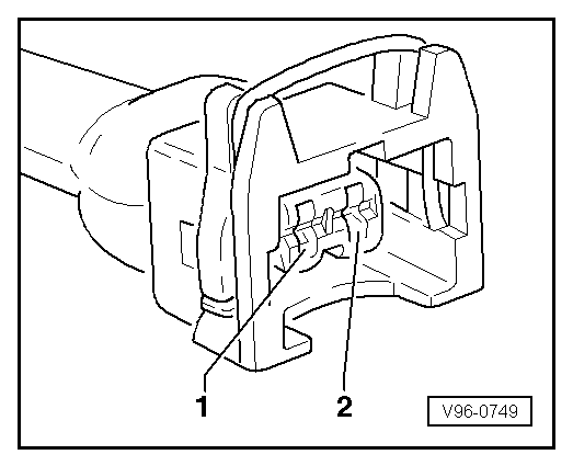
Checking activated charcoal filter system solenoid valve 1 -N80

Special tools and workshop equipment required

  • ◆ V.A.G 1526 A
  • ◆ V.A.G 1527 B
  • ◆ V.A.G 1594 A
  • ◆ V.A.G 1598/31
  • ◆ VAS 5051 with VAS 5051/1
  • or
  • ◆ V.A.G 1551 with V.A.G 1551/3 A

Note:

The activated charcoal filter system solenoid valve 1 is also referred to in this context as fuel tank breather valve of ACF valve.

Testing for leaks

When there is no electrical supply, solenoid valve remains closed.

  • ‒ Disconnect hoses from ACF valve but leave the electrical connector plugged in.
  • ‒ Connect auxiliary hose to one connection of ACF valve.
  • ‒ Connect up vehicle diagnostic, measurement and information system VAS 5051 or fault reader V.A.G 1551 and select engine electronics control unit with "Address word" 01 .
    For this purpose, the ignition must be switched on.
  • ‒ Start final control diagnosis and actuate ACF solenoid -N80 .
 
→ Indicated on display:
Final control diagnosis    ⇒
Solenoid valve 1 for activated charcoal filter -N80
  • ◆ The valve should click...
  • ◆ ...and should open and close (check by blowing into the auxiliary hose).

If the injector does not click:

  • ‒ Checking internal resistance to ACF valve.

If valve does not open and close properly:

  • ‒ Replace -N80 solenoid valve for active carbon canister.

Checking internal resistance

  • ‒ Unplug connector on ACF valve.
 
A24-0241
  • ‒ → Connect multimeter to injector to measure resistance.
    • ‒ Specified value: 22...30 ω

If specified value is not attained:

  • ‒ Replace -N80 solenoid valve for active carbon canister.

If specified value is attained:

  • ‒ Check the voltage supply
    .

Checking power supply

Test requirements:

  • ● Fuse for ACF valve OK.

=> Current Flow Diagrams, Electrical Fault-Finding and Fitting Locations

  • ● Check pump relay OK; checking .

Note:

The ACF valve receives its power supply via the fuel pump relay.

  • ‒ Unplug connector on ACF valve.
 
V96-0749
  • ‒ → Connect voltage tester V.A.G 1527 B as follows:

Connector
contact

Measure to

1

Engine earth

  • ‒ Operate the starter briefly (the engine may start).
    • ‒ The LED should light up.

If the LED does not light up:

  • ‒ Check the wiring from contact 1 on the connector via the fuse to the fuel pump relay for an open circuit.

=> Current Flow Diagrams, Electrical Fault-Finding and Fitting Locations

  • ‒ Rectify open circuit, if necessary.

If the LED lights up:

  • ‒ Check actuation.

Checking actuation

 
V96-0749
  • ‒ → Connect voltage tester V.A.G 1527 B to contacts 1 (positive) and 2 of the connector.
  • ‒ Initiate final control diagnosis and actuate ACF solenoid -N80 .
    • ‒ The LED should flash.

If the LED lamp does not flash or if it lights up continuously:

  • ‒ Connect the V.A.G 1598/31 test box to wiring harness leading to engine control unit; the engine control unit should not be connected => Page 24-17.
 
V96-0749
  • ‒ → Check for open circuit and short to positive or earth in the following wiring connection:

Connector
contact

Test box V.A.G 1598/31
Socket

2

64

  • ‒ Rectify any open/short circuit as necessary.

If the wiring is OK:

  • ‒ Fit a new engine control unit => Page 24-22.

Checking electronic engine power control (electronic throttle) > < Checking fuel tank breather