audi Workshop Repair Guides

Audi Workshop Service and Repair Manuals

Removing and installing Lambda probe > < Check lambda probe and lambda control after catalytic converter
Motronic Fuel Injection and Ignition System (6-cylinder)
Checking lambda control
Check lambda probe heater for lambda probes upstream or downstream of cat
 
G24-0024

Special tools and workshop equipment required

  • ◆ V.A.G 1526 A
  • ◆ V.A.G 1594 A
  • ◆ V.A.G 1598/31
  • ◆ V.A.G 1788/10
  • ◆ VAS 5051 with VAS 5051/1
  • or
  • ◆ V.A.G 1551 with V.A.G 1551/3 A

Note:

The lambda probe heating circuit is monitored by the self-diagnosis system.

Interrogate fault memory.

  • ‒ Connect vehicle diagnostic, testing and information system VAS 5051 or fault reader V.A.G 1551 and select engine electronics control unit with "Address word" 01 => Page 01-3
    For this purpose, the engine must be running at idle speed
 
→ When indicated on display:
Rapid data transfer     HELP
Select function XX
  • ‒ Enter "08" to select the function "Reading measured value block" and confirm entry with Q key.
 
→ When indicated on display:
Reading measured value block    Q
Enter display group number XXX
  • ‒ Enter "041" for "display group number 041" and confirm entry with Q key.
 
→ When indicated on display:
Read measured value block    41    ⇒
    1    2    3    4
  • ‒ Check specified values in display zones 1 and 3.

Note:

By increasing the engine speed the achieving of the specified values can be accelerated.

Display zones

1

2

3

4

Display group 041: Lambda probe heating (Bank 1) at idling speed

Display

xxx kOhm

---

xxx kOhm

---

Display

Bank 1, probe 1

Status of heating

Bank 1, probe 2

Status of heating

Range

Htg. bC. ON
Htg. bC. OFF

Htg. aC. ON
Htg. aC. OFF

Specified value

0...0.9 kOhm

Htg. bC ON/OFF

0...0.9 kOhm

Htg.aC ON/OFF

Important notes on display zones 1, 2, 3 and 4:

  • ◆ If the lambda probes have not reached their operating temperature there is no display in display zones 1 and 3, i.e. both zones are empty. (Increase engine speed to reach specified values.)
  • ◆ After reaching the operating temperature of both lambda probes a resistance of lower than 0.9 Ohm must be shown in display zones 1 and 3.
  • ◆ Only carry on with test when a resistance value lower than 0.9 kOhm is shown in display zones 1 and 3.
  • ◆ At certain operating points, the engine control unit "cycles" the earth for the lambda probe heating. This means that at these points the lambda probe heating is continuously switched on and off. It is also possible that "Htg. bC OFF" or "Htg. aC OFF" is displayed as specified value in display zones 2 and 4.
  • ‒ Press Ckey.
 
→ When indicated on display:
Reading measured value block    Q
Enter display group number XXX
  • ‒ Enter "042" for "display group number 042" and confirm entry with Q key.
 
→ When indicated on display:
Read measured value block    42    ⇒
    1    2    3    4
  • ‒ Check specified values in display zones 1 and 3.

Display zones

1

2

3

4

Display group 042: Lambda probe heating (Bank 2) at idling speed

Display

xxx kOhm

---

xxx kOhm

---

Display

Bank 1, probe 2

Status of heating

Bank 2, probe 2

Status of heating

Range

Htg. bC. ON
Htg. bC. OFF

Htg. aC. ON
Htg. aC. OFF

Specified value

0...0.9 kOhm

Htg.bC ON/OFF

0...0.9 kOhm

Htg.aC ON/OFF

Important notes on display zones 1, 2, 3 and 4:

  • ◆ If the lambda probes have not reached their operating temperature there is no display in display zones 1 and 3, i.e. both zones are empty. (Increase engine speed to achieve specified values.)
  • ◆ After reaching the operating temperature of both lambda probes a resistance of lower than 0.9 Ohm must be shown in display zones 1 and 3.
  • ◆ Only carry on with test when a resistance value lower than 0.9 kOhm is shown in display zones 1 and 3.
  • ◆ In certain operating points, the engine control unit "cycles" for the lambda probe heating. This means that at these points the lambda probe heating is continuously switched on and off. It is also possible that "Htg. bC OFF" or "Htg. aC OFF" is displayed as specified value in display zones 2 and 4.

If specified value is not attained:

  • ‒ Check the voltage supply to the lambda probe heating => Page 24-126.
  • ‒ Check lambda probe signal line and actuation => Page 24-119.

Checking voltage supply for lambda probe heating

Fitting location of connectors => Fitting location overview Page 24-5

Test requirements:

  • ● Fuse for Lambda probe heating OK.

=> Current Flow Diagrams, Electrical Fault-Finding and Fitting Locations

  • ● Check pump relay OK; checking .
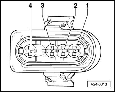
  • ‒ Disconnect 4- pin connector to relevant Lambda probe.
 
A24-0013
  • ‒ → Connect multimeter between contacts 1 and 2 to measure voltage.
  • ‒ Start the engine.
    • ‒ Specified value: approx. battery voltage, may fluctuate

Notes:

  • ◆ At certain operating points, the engine control unit "cycles" the earth for the lambda probe heating. This means that at these points, the earth is continuously switched on and off. For this reason, the voltage reading on the tester may fluctuate.
  • ◆ Points at which Lambda probe heating is switched on and off by engine control unit can be observed in "Reading measured value block" function, display group number 041 and 042.

If no voltage is present:

 
A24-0013
  • ‒ → Connect multimeter as follows to measure voltage:

Connector
contact

Measure to

1 (positive)

Vehicle earth

  • ‒ Operate starter briefly.
    • ‒ Specified value: approx. battery voltage

If no voltage is present:

  • ‒ Check the wiring from contact 1 on the connector via the fuse to the fuel pump relay for an open circuit.

=> Current Flow Diagrams, Electrical Fault-Finding and Fitting Locations

If voltage supply is OK:

 
A24-0013
  • ‒ → Connect multimeter as follows to measure voltage:

Connector
contact

Measure to

2 (earth actuation by engine control unit)

Battery positive

  • ‒ Start the engine.
    • ‒ Specified value: approx. battery voltage, may fluctuate
  • ‒ Switch ignition off.

If no voltage is present:

  • ‒ Connect the V.A.G 1598/31 test box to wiring harness leading to engine control unit; the engine control unit should not be connected => Page 24-17.
 
A24-0013
  • ‒ → Check for open circuit in the following wiring connections:
  • ● Lambda probe heating -Z19 Bank 1 upstream of Cat:

Connector
contact

Test box V.A.G 1598/31
Socket

2

5

  • ● Lambda probe heating -Z28 Bank 2 upstream of Cat:

Connector
contact

Test box V.A.G 1598/31
Socket

2

4

  • ● Lambda probe heating -Z29 Bank 1 downstream of Cat:

Connector
contact

Test box V.A.G 1598/31
Socket

2

63

  • ● Lambda probe heating -Z30 Bank 2 downstream of Cat:

Connector
contact

Test box V.A.G 1598/31
Socket

2

6

If no wiring fault is detected:

  • ‒ Replace appropriate lambda probe.
  • ‒ Read out readiness code => Page 01-71.

Removing and installing Lambda probe > < Check lambda probe and lambda control after catalytic converter