audi Workshop Repair Guides

Audi Workshop Service and Repair Manuals

Checking intake air system for leaks (unmetered air) > < Fuel pump relay -J17 and actuation
Motronic Fuel Injection and Ignition System (6-cylinder)
Servicing Motronic injection system
Checking air mass meter -G70
 
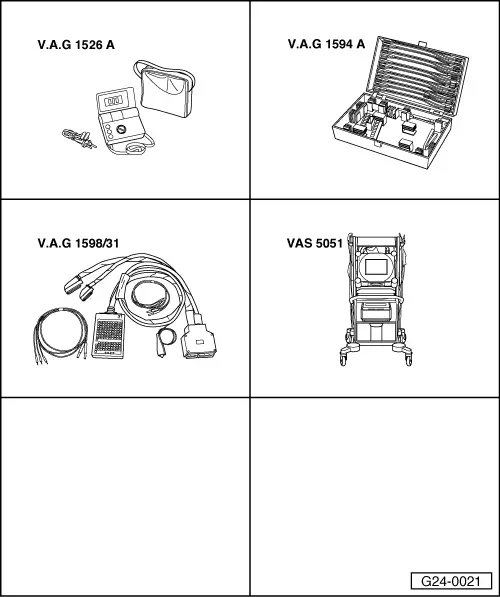
G24-0021

Special tools and workshop equipment required

  • ◆ V.A.G 1526 A
  • ◆ V.A.G 1594 A
  • ◆ V.A.G 1598/31
  • ◆ VAS 5051 with VAS 5051/1
  • or
  • ◆ V.A.G 1551 with V.A.G 1551/3 A

Test requirements:

  • ● Coolant temperature at least 80 °C.
  • ● Electrical consumers switched off (radiator fan must not run during the test).
  • ● Air conditioning switched off.
  • ● Fuse for air mass meter OK.

=> Current Flow Diagrams, Electrical Fault-Finding and Fitting Locations

checking function

  • ‒ Connect vehicle diagnostic, testing and information system VAS 5051 or fault reader V.A.G 1551 and select engine electronics control unit with "Address word" 01
    For this purpose, the engine must be running at idle speed
 
→ When indicated on display:
Rapid data transfer     HELP
Select function XX
  • ‒ Enter "04" to select "Start basic setting" and confirm with Q key.

Note:

During basic setting, the solenoid valve for the active carbon canister (valve -N80) is closed and the air conditioner compressor is switched off.

 
→ When indicated on display:
Basic setting      Q
Enter display group number XXX
  • ‒ Enter "002" for "display group number 002" and confirm entry with Q key.
 
→ When indicated on display:
System in basic setting 2    ⇒
    1    2    3    4
  • ‒ Check specified values for load recognition in display zones 3 and 4.

Display zones

1

2

3

4

Display group 002: Intake airflow at idle and operating temperature

Display

xxx rpm

xx.x %

x.x ms

xxx.x g/s

Display

Engine speed

Load

Average injection period

Air mass

Range

630..6800 rpm

7...100 %

1.0...21.0 ms

1.0...160 g/s

Specified value

670...770 rpm 1)
720...820 rpm2)
630...730 rpm3)

12.0...26.0 %

1.0...4.0 ms

1.0...5.0 g/s

Note

---

---

If specified value is not attained: Evaluation, display zone 3

If specified value is not attained: Evaluation, display zone 4

1)    2.4 litre front and four-wheel drive 2) 2.8 litre front wheel drive 3) 2.8 litre four-wheel drive

If specified values are attained:

  • ‒ Press the ⇒key.
 
→ Indicated on display (function selection):
Rapid data transfer     HELP
Select function XX

Interpreting display group 002

Display zone: 3

Possible causes of fault

Fault remedy

Less than 1.0 ms

- Lower values can only occur when vehicle is on overrun

Greater than 4.0 ms

- Engine load from ancillaries

- Eliminate load (air conditioner system/ power steering/alternator)

- Poor idling (not running on all cylinders)

- Test spark plugs
Check injectors

- Throttle valve control unit -J338 defective

- Check throttle valve control unit .

Interpreting display group 002

Display zone: 4

Possible causes of fault

Fault remedy

Less than 1.0 g/s

- Large quantity of unmetered air between intake manifold and airflow meter
- Voltage supply to airflow meter or wiring to engine control unit

- Test for leaks (unmetered air) in intake air system

Greater than 5.0 g/s

- Engine load from ancillaries

- Eliminate load (air conditioner system/ power steering/alternator)

- Voltage supply to airflow meter or wiring to engine control unit

- Check voltage supply and/or wiring => Page 24-65

Testing voltage supply to air mass meter

  • ‒ Disconnect connector from intake air temperature sensor.
 
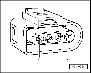
A24-0094
  • ‒ → Connect multimeter as follows to measure voltage.

Connector
contact

Measure to

3

Engine earth

  • ‒ Operate starter briefly.
    • ‒ Specified value: approx. battery voltage

Note:

Voltage supply to airflow meter is from fuel pump relay.

If specified value is not attained:

  • ‒ Check the wiring from contact 3 on the connector via the fuse to the fuel pump relay for open circuit or short to earth:

=> Current Flow Diagrams, Electrical Fault-Finding and Fitting Locations

  • ‒ Rectify any open/short circuit as necessary.
 
A24-0094
  • ‒ → Connect hand-held multimeter to contact 2 and contact 3 of the connector to measure voltage.
  • ‒ Operate starter briefly.
    • ‒ Specified value: approx. battery voltage

Note:

Engine control unit earth is present at contact 2 of the connector.

If specified value is not attained:

  • ‒ Check the wiring connections
    .
 
A24-0094
  • ‒ → Connect hand-held multimeter to contact 1 and contact 2 of the connector to measure voltage.
  • ‒ Switch the ignition on.
    • ‒ Specified value: approx. 5 V

If specified value is not attained:

  • ‒ Check the wiring connections
    .

Check wiring to airflow meter.

Note:

The signal wire is also checked during the wiring check.

  • ‒ Connect the V.A.G 1598/31 test box to wiring harness leading to engine control unit; the engine control unit should not be connected => Page 24-17.
 
A24-0094
  • ‒ → Check for open circuit and short to positive or earth in the following wiring connections:

Connector
contact

Test box V.A.G 1598/31
Socket

1

53

2

27

4

29

  • ‒ Rectify any open/short circuit as necessary.
  • ‒ Additionally check all wires for short to one another.

If the wiring is OK:

  • ‒ Renew air mass meter -G70.

Checking intake air system for leaks (unmetered air) > < Fuel pump relay -J17 and actuation