
A4 Mk1
|
Checking ignition system
Checking coolant temperature sender -G62
|
 |
|
|
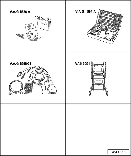
Special tools, testers and workshop equipment required
Installation position => Overview installation positions - Page 24-5 Test requirements:
Test sequence
|
| → Display readout: |
|
||
|
| → Display readout: |
|
||
|
| → Display readout: |
|
|||||||||||||||||||||||||||||||||||
If there is no realistic readout in display zone 3: Note: Access to coolant temperature sender involves removing intake hose between airmass meter and noise insulation.
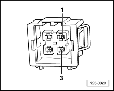
Coolant temperature sender with square plug: | ||||||||||||||||||||||||||||||||||||
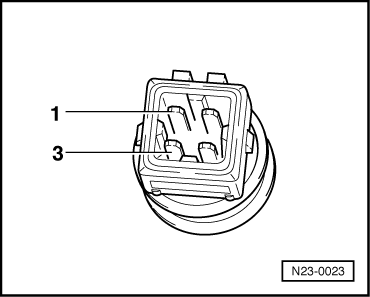 |
|
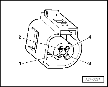
Coolant temperature sender with oval plug: |
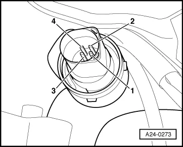 |
|
All models: Scale A shows resistance values for temperature range 0...50 oC and scale B the values for temperature range 50...100 oC. |
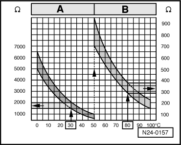 |
|
|
→ Examples:
If the specified value is not attained:
If the specified value is attained:
|
 |
||||||
|
Coolant temperature sender with square plug:
Coolant temperature sender with oval plug: |
 |
|||||||
All models:
If no wiring fault is detected:
|