audi Workshop Repair Guides

Audi Workshop Service and Repair Manuals

Motronic injection and ignition system (6 cyl. turbo) > < Checking knock sensors
Motronic fuel injection and ignition system (6 cyl.)
Checking ignition system
Checking Hall sender
 
G24-0022

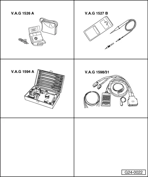
Special tools, testers and workshop equipment required

  • ◆ V.A.G 1526 A
  • ◆ V.A.G 1527 B
  • ◆ V.A.G 1594 A
  • ◆ V.A.G 1598/31

Installation position => Overview installation positions - Page 24-5

Notes:
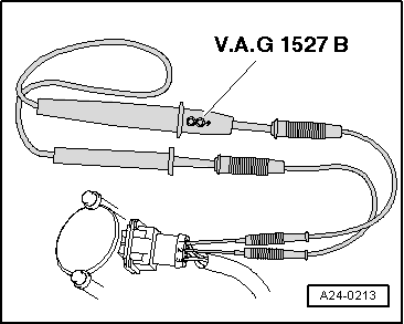
  • ◆ Hall sender -G40 is located at rear of left-hand cylinder head (bank 2).
  • ◆ Hall sender -G163 is located at front of right-hand cylinder head (bank 1).

Checking actuation

  • ‒ Push back rubber grommet of connector for respective Hall sender but leave connector attached.
 
A24-0213
  • ‒ → Connect up voltage tester V.A.G 1527 B between receptacle 2 (Hall sender signal) and receptacle 1 (positive).

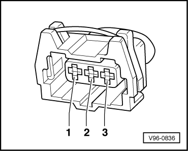
Note:

Receptacles are numbered accordingly on the back of the connector.

  • ‒ Operate the starter for a few seconds.
    • ‒ The LED should flash briefly every second engine revolution.

Note:

Voltage testers with a low current draw continue to glow faintly between impulses from the engine control unit (rather than going out completely) and become much brighter when receiving an impulse.

If LED does not flash:

Checking voltage supply

  • ‒ Disconnect connector from relevant Hall sender.
  • ‒ Switch on the ignition.
 
V96-0836
  • ‒ → Connect multimeter as follows to measure voltage:

Connector
Contact

Measure to

1

Engine earth

    • ‒ Specified value: approx. 5 V.

Checking signal wire

 
V96-0836
  • ‒ → Connect multimeter as follows to measure voltage:

Connector
Contact

Measure to

2

Engine earth

    • ‒ Specified value: approx. battery voltage

Checking earth wire

  • ‒ Connect multimeter as follows to measure voltage:

Connector
Contact

Measure to

3

Battery positive

  • ‒ Rectify any open/short as necessary.

If the specified values are all achieved and the diode test lamp does not flash (measured between contacts 1 and 2 with starter connector attached),

  • ‒ Replace relevant Hall sender.

If the specified values are not attained:

Checking wiring between Hall sender and engine control unit.

  • ‒ Connect the V.A.G 1598/31 test box to wiring harness leading to engine control unit; the engine control unit should not be connected .
 
V96-0836
  • ‒ → Check for open circuit and short to earth/positive or earth in the following wiring connections:

Hall sender - G40 (Bank 2)

Connector
Contact

Test box V.A.G 1598/31
Bush

1 (positive)

98

2 (signal)

86

3 (earth)

108

Hall sender -G163 (Bank 1)

Connector
Contact

Test box V.A.G 1598/31
Bush

1 (positive)

98

2 (signal)

87

3 (earth)

108

  • ‒ Rectify any open/short as necessary.
  • ‒ If a trial erasure of the fault memory is followed by the replaced indication of a fault relating to the camshaft sensor (Hall sender) although all previous tests were OK, the following faults are possible:
    • ‒ Rotor ring for Hall sender misaligned

Check phase position of Hall sender

  • ‒ Connect up vehicle diagnosis, measurement and information system VAS 5051 or fault reader V.A.G 1551 and select engine electronics control unit with "Address word" 01 => Page 01-3.
    When doing this the engine must be running at idle speed
 
→ Display readout:
Rapid data transfer    HELP
Select function XX
  • ‒ Enter "08" to select the function "Reading measured value block" and confirm entry with Q key.
 
→ Display readout:
Reading measured value block    Q
Enter display group number XXX
  • ‒ Enter "093" to select "Display Group 093" and confirm entry with the Q key.
 
→ Display readout:
Reading measured value block 93    ⇒
    1    2    3    4
  • ‒ Check specified results for Hall sender.

Display zones

1

2

3

4

Display Group 093: Phase locations of Hall senders (Bank 1 and Bank 2), engine idling

Display

xxx rpm

xx %

Crankshaft

Crankshaft

Display

Engine speed

Engine load

Phase location
Bank 1

Phase location
Bank 2

Range

0...6800 rpm

14...100 %

-20.3....14.8 o Crankshaft

-20.3....14.8 o Crankshaft

Specified value

670...770rpm

14...28 %

0 ± 6 o Crankshaft

0 ± 6 o Crankshaft

Note:

If the specified results are not achieved, unscrew Hall sender and check to ensure that the rotor ring is correctly mounted on the camshaft (if it is incorrectly installed, the catch will be pressed flat when the securing screw is tightened).

Motronic injection and ignition system (6 cyl. turbo) > < Checking knock sensors