|
Special tools, testers and workshop equipment required
-
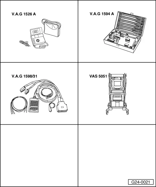
◆ V.A.G 1526 A
-
◆ V.A.G 1594 A
-
◆ V.A.G 1598/31
-
◆ VAS 5051 with VAS 5051/1
-
◆ V.A.G 1551 with V.A.G 1551/3 A
Notes:
-
◆ Data is exchanged between individual control units by means of a bus system.
-
◆ "Bus" is used to describe a system that transports and distributes data.
-
◆ The wires between the control units that are used to transfer the data are known as signal wires.
-
◆ These signal wires are used for serial transmission of data, i.e. data is sent to each of the connected control units in turn.
Testing the bus system
The fault table includes instructions to test the data exchange between engine control unit, gearbox control unit and ABS control unit.
-
‒ Interrogate the fault memory of the gearbox control unit.
=> Automatic gearbox, Self-diagnosis; Repair group 01; Performing self-diagnosis
-
‒ Interrogate the fault memory of the ABS control unit.
=> Running gear FWD and 4WD; Repair Group 01; Self-diagnosis; Electrical tests
If a fault is displayed relating to "Databus..." or "...communication":
-
‒ Check whether appropriate engine, gearbox and ABS control units have been fitted in the vehicle. If they have:
-
‒ Switch off ignition.
-
‒ Connect the V.A.G 1598/31 test box to wiring harness leading to engine control unit; engine control unit should not be connected .
-
‒ Use current flow diagram to check for open circuit/short in data lines from engine control unit pin 6 and 58 (contacts 79 and 77 on engine control unit are used for data lines to infinitely variable speed gearbox control unit; refer also to "Important Note") to gearbox control unit (if fitted) or to ABS control unit.
=> "Current Flow Diagrams, Electrical Fault Finding and Installation locations" binder
Important note:
Contacts 79 and 77 on the engine control unit are used for the data wires to the control unit for the infinitely variable speed gearbox (if fitted). For all other "bus users" measurements are to be taken at contacts 60 and 58 on engine control unit.
-
‒ If the wiring is OK, try installing a new engine/gearbox/ABS control unit in turn.
|