
A4 Mk1
|
Servicing Motronic injection system
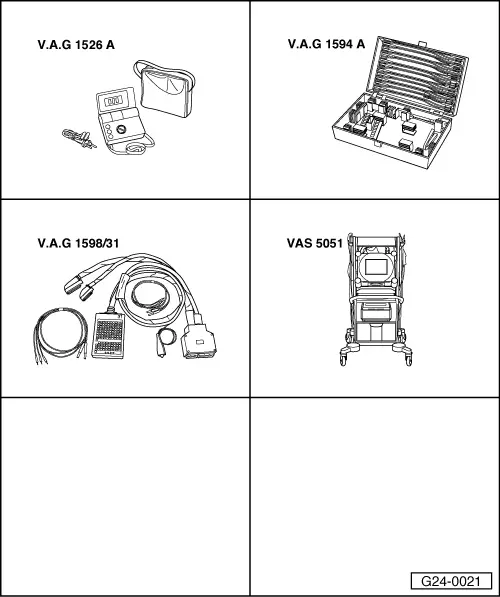
Checking air mass meter -G70
|
| → Display readout: |
|
||
Note: During basic setting, the solenoid valve for the active carbon canister (valve -N80) is closed and the air conditioning compressor is switched off. |
| → Display readout: |
|
||
|
| → Display readout: |
|
||||||||||||||||||||||||||||||||||||||||
If the specified value is attained:
| |||||||||||||||||||||||||||||||||||||||||
| → Display readout (function selection): |
|
|||||||||||||||||||||||||||
|
Interpreting display group 002
Interpreting display group 002
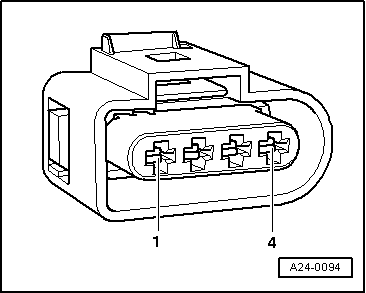
Testing voltage supply to air mass meter
|
 |
|||||
Note: Voltage supply to airflow meter is from fuel pump relay. |
 |
|
|
If the specified value is not attained:
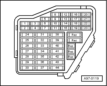
=> "Current Flow Diagrams, Electrical Fault Finding and Installation locations" binder
|
|
|
Note: Engine control unit earth is present at contact 2 of the connector. If the specified value is not attained:
|
|
|
If the specified value is not attained:
Check wiring to airflow meter. Note: The signal wire is also checked during the wiring check.
|
|
|||||||||
If the wiring is OK:
|