audi Workshop Repair Guides

Audi Workshop Service and Repair Manuals

Checking control unit voltage supply > < Technical data for ignition system
Motronic injection and ignition system (4-cyl.)
Testing ignition system
Testing dual-spark ignition system (2 coils)

Note:

Each ignition coil is combined with its output stage as a single component.

It is not possible to test this component using conventional measuring equipment and methods.

If there is a fault in the ignition system:

  • ‒ Test power supply
  • ‒ Test activation of output stages
    => Page 28-6

If the tests do not reveal any faults but there is still no ignition spark:

  • ‒ Renew output stage with ignition coils.

Testing power supply

 
A28-0003
  • ‒ Unplug connector from ignition coils
    => Fitting locations overview, Page 24-5.
  • ‒ → Connect hand-held multimeter (voltage test range) to contact 4a and to earth.
  • ‒ Switch ignition on.
  • Specification: approx. battery voltage

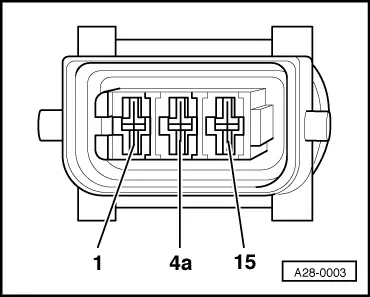
If the specification is not obtained:

  • ‒ Check the wiring.

=> Current flow diagrams, Electrical fault finding and Fitting locations binder

Testing activation of output stages

  • ‒ Unplug the connectors from all four injectors.

Note:

It is important to ensure that no fuel is injected during the test as this would damage the catalytic converter. The connectors on the injectors must therefore be unplugged.

  • ‒ Unplug connector on ignition coils
    => Fitting locations overview, Page 24-5.
  • ‒ Switch ignition on.
 
A28-0003
  • ‒ → Connect diode test lamp V.A.G 1527 to the following sockets on the connector:
  • ‒ Operate starter for a few seconds.

3-pin connector on wiring harness, socket

Specification

1 + earth

Diode test lamp should

15 + earth

flash (brief impulse)

If the specifications are not obtained:

  • ‒ Switch off ignition.
  • ‒ Connect test box V.A.G 1598/31 to wiring harness for engine control unit. Do not connect to the engine control unit itself.
    => Page 24-10.
 
A28-0003

Check the following wiring connections for open circuits and short to positive or earth.

3-pin connector on wiring harness, socket

Test box V.A.G 1598/22, socket

1

103

15

102

  • ‒ Rectify any open/short circuit as necessary.

=> Current flow diagrams, Electrical fault finding and Fitting locations binder

Checking control unit voltage supply > < Technical data for ignition system