audi Workshop Repair Guides

Audi Workshop Service and Repair Manuals

Testing intake air temperature sender -G42 > < Testing Motronic current supply relay -J271
Motronic injection and ignition system (4-cyl.)
Servicing Motronic injection system
Testing air mass meter -G70

Test conditions

  • ● Coolant temperature at least 80 °C
  • ● Electrical consumers switched off (radiator fan must not run during test)
  • ● Air conditioner switched off
  • ● Fuse for air mass meter OK

=> Current flow diagrams, Electrical fault finding and Fitting locations binder

Testing operation

  • ‒ Connect vehicle diagnostic, testing and information system VAS 5051 (or fault reader V.A.G 1551) and select engine electronics control unit by entering address word "01" ( .)
    When doing this the engine must be idling.
 
→ Indicated on display:
Rapid data transfer    HELP
Select function XX
  • ‒ Press keys 0 and 4 for the function "Introduction of basic setting" and confirm entry with the Q key.

Note:

During the basic setting the engine control unit closes the activated charcoal filter solenoid valve (ACF valve -N80) and switches off the air conditioner compressor.

 
→ Indicated on display:
Basic setting    Q
Enter display group number    XXX
  • ‒ Press keys 0, 0 and 2 for Display Group 02 and confirm entry with the Q key.
 
→ Indicated on display:
System in basic setting 2    ⇒
    1    2    3    4
  • ‒ Check display values for engine load.

Display zones

1

2

3

4

Display Group 2: Intake air mass at idling speed with engine at normal operating temperature

Display

xxx rpm

xx.x %

x.x ms

xxx.x g/s

Indicates

Engine speed
(in steps of 40 rpm)

Load

Average injection period

Air mass

Range

min.: 750 rpm
max.: 6800 rpm

min.: 0 %
max.: 120.0 %

min.: 0 ms
max.: 100 ms

min.: 0 g/s
max.: 360.0 g/s

Specification

810...910 rpm

15.0....25.0 %

1.0....4.0 ms

2.0....4.5 g/s

Note

---

---

If specification is not met: =>reading display zone 3, Page 24-46

If specification is not met: =>reading display zone 4, Page 24-47

If the specification is obtained:

  • ‒ Press ⇒key.
  • ‒ Press keys 0 and 6 for the function "End output" and confirm entry with the Q key.
  • ‒ Switch off the ignition.

Reading Display Group 002

Display zone 3

Possible cause of fault

Fault remedy

Less than 1.0 ms

- Lower values can only occur when vehicle is on overrun

More than 4.0 ms

- Load on engine due to ancillaries

- Eliminate load (air conditioner, power steering, alternator)

- Rough idling (engine not running on all cylinders)

- Test spark plugs
Test injectors => Page 24-31

- Throttle valve control part -J338 defective

- Test throttle valve control part
=> Page 24-145

Reading Display Group 002

Display zone 4

Possible cause of fault

Fault remedy

Less than 2.0 g/s

- Large quantity of unmetered air between intake manifold and air mass meter
- Voltage supply to air mass meter or wiring to
- engine control unit

- Rectify air leaks (unmetered air)
Test voltage supply and wiring
=> Page 24-48

More than 4.5 g/s

- Load on engine due to ancillaries

- Eliminate load (air conditioner, power steering, alternator)

- Voltage supply to air mass meter or wiring to
- engine control unit

- Test voltage supply and wiring
=> Page 24-48

Testing power supply to air mass meter

 
A23-0058
  • ‒ Unplug connector from air mass meter.
  • ‒ → Connect hand-held multimeter (voltage measurement range) between engine earth and socket 2 of connector.
  • ‒ Operate the starter briefly.
  • Specification: approx. battery voltage

Note:

The air mass meter receives its voltage supply via the fuel pump relay.

If the reading does not match the battery voltage:

  • ‒ Test for open circuit or short to earth in wiring between fuel pump relay and socket 2 on connector via fuse. Repair if necessary.

=> Current flow diagrams, Electrical fault finding and Fitting locations binder

If specification is met:

  • ‒ Test earth connection from control unit => Page 24-49.

Testing earth connection

 
A23-0058
  • ‒ → Connect hand-held multimeter (voltage measurement range) between sockets 2 and 3 of connector.
  • ‒ Operate the starter briefly.
  • Specification: approx. battery voltage

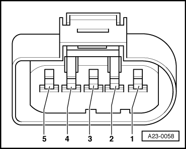
Note:

Socket 3 on the connector is the earth connection from the engine control unit.

If the specification is not attained:

  • ‒ Test the wiring => Page 24-50.
 
A23-0058
  • ‒ → Connect hand-held multimeter (voltage measurement range) between sockets 3 and 4 of connector.
  • ‒ Switch ignition on.
  • Specification: approx. 5 V

If the specification is not attained:

  • ‒ Test the wiring => Page 24-50.

Testing wiring for air mass meter

Note:

The signal wire is also tested in the wiring test.

 
A23-0058
  • ‒ Connect test box V.A.G 1598/31 to wiring harness for engine control unit. Do not connect to the engine control unit itself.
    => Page 24-10.
  • ‒ → Test for open circuit and short to positive or earth in the following wiring connections:

Connector for air mass meter -G70, socket

Test box V.A.G 1598/31, socket

3

27

4

53

5 (signal wire)

29

  • ‒ Rectify short circuit or open circuit if necessary.

=> Current flow diagrams, Electrical fault finding and Fitting locations binder

  • ‒ Test all wires for short circuits with each other.

Connector for air mass meter -G70, socket

Test box V.A.G 1598/31, socket

3

53 and 29

4

27 and 29

5 (signal wire)

27 and 53

  • Specification: infinity ω(open circuit)
  • ‒ If the wiring and the power supply are OK, fit a new air mass meter -G70.

Testing intake air temperature sender -G42 > < Testing Motronic current supply relay -J271