audi Workshop Repair Guides

Audi Workshop Service and Repair Manuals

Testing Motronic current supply relay -J271 > < Checking injectors
Motronic injection and ignition system (4-cyl.)
Servicing Motronic injection system
Testing fuel pump relay -J17 and activation

The fuel pump and some of the injection system components are powered via the fuel pump relay -J17.

The fuel pump relay -J17 will only close if the engine is turning over. In other words, the relay is only earthed (via the engine control unit) when the engine control unit is receiving engine speed impulses.

Test conditions

 
A24-0100
  • ● Battery voltage OK.

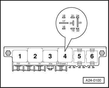
Functional test of fuel pump relay

→ Fitting location of fuel pump relay: micro central electrics behind storage compartment on driver's side, relay position 4.

  • ‒ Connect vehicle diagnostic, testing and information system VAS 5051 (or fault reader V.A.G 1551) and select engine electronics control unit by entering address word "01" ( .)
    When doing this the ignition must be switched on.
 
A24-0100
  • ‒ Start final control diagnosis => Page 01-42. The fuel pump must be running.
  • → The fuel pump relay should pick up and the fuel pump should run.

If the relay does not pick up:

  • ‒ Test activation of fuel pump relay.

If fuel pump does not run:

  • ‒ Test activation of fuel pump and other components .

Testing activation of fuel pump relay

  • ‒ Switch off ignition.
  • ‒ Connect test box V.A.G 1598/31 to wiring harness for engine control unit. Do not connect to the engine control unit itself.
    => Page 24-10.
  • ‒ Connect sockets 65 and 2 of test box to each other using auxiliary cable from V.A.G 1594.
  • ‒ Switch ignition on.
  • Specification: the fuel pump relay (relay position 4) should pick up.
 
A24-0100

If the relay picks up now but not during the final control diagnosis:

  • ‒ Replace engine control unit .

If the relay does not pick up:

  • ‒ Switch off ignition.
  • ‒ → Disconnect fuel pump relay from relay panel (relay position 4).

 
A24-0100
  • ‒ → Connect hand-held multimeter (voltage measurement range) between earth and contact 19 on relay panel.
  • ‒ Switch ignition on.
  • Specification: approx. battery voltage

If the specification is not obtained:

 
A24-0100
  • ‒ Check the wiring.

=> Current flow diagrams, Electrical fault finding and Fitting locations binder

If the specification is obtained:

  • ‒ Switch off ignition.
  • ‒ → Test for open circuit and short to positive or earth in the following wiring connections:

Micro central electrics on left of driver's footwell, relay position 4
Contact

Test box V.A.G 1598/31


Socket

16

65

 
A97-0119
  • ‒ Rectify any open/short circuit as necessary.

If no wiring fault is detected:

  • ‒ Fit a new fuel pump relay -J17.

Testing activation for fuel pump and other components

  • ‒ → Remove fuses 28 and 29 (=>current flow diagram).
 
A97-0119
  • ‒ Start final control diagnosis => Page 01-42.
  • ‒ → Connect hand-held multimeter (voltage measurement range) between earth and either left or right contact on the following fuses (only one contact on each fuse is live):

Fuse No.

Specification for left or right contact

28

approx. battery voltage

29

approx. battery voltage

If the specifications are not obtained:

  • ‒ Check wiring

=> Current flow diagrams, Electrical fault finding and Fitting locations binder

If no wiring fault is detected:

  • ‒ Fit a new fuel pump relay -J17.

Testing Motronic current supply relay -J271 > < Checking injectors