audi Workshop Repair Guides

Audi Workshop Service and Repair Manuals

Testing vacuum system > < Testing operation
Motronic injection and ignition system (4-cyl.)
Testing intake manifold change-over function
Testing intake manifold change-over valve -N156

Fitting location .

Testing intake manifold change-over valve -N156

  • ‒ Run engine at idling speed for 2 or 3 minutes to build up vacuum.
  • ‒ Switch engine off.
  • ‒ Switch ignition on.
 
→ Perform final control diagnosis and activate intake manifold change-over valve => Page 01-42.
Final control diagnosis    ⇒
Intake manifold press. change valve -N156

The valve should click (clicking can be heard and felt). After 1 minute the final control diagnosis is terminated.

  • ‒ If the valve does not click, switch off the ignition.
 
A24-0222
  • ‒ Unplug connector from intake manifold change-over valve -N156.
  • ‒ → Measure resistance between contacts of solenoid valve using V.A.G 1526.
  • Specification: 25...35 ω
  • ‒ If the reading does not match the specification, renew intake manifold change-over valve -N156.

If the reading matches the specification, test voltage supply
=> Page 24-125.

 
V96-0749

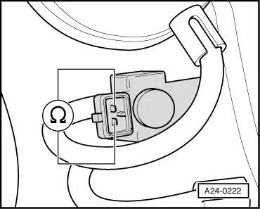
Testing voltage supply to intake manifold change-over valve

-N156

  • ‒ → Connect diode test lamp V.A.G 1527 between engine earth and socket 1 on connector using test leads from auxiliary test set V.A.G 1594.
  • ‒ Operate the starter briefly.

The diode test lamp should light up.

  • ‒ If the diode test lamp does not light up:
  • ‒ Test fuse for intake manifold change-over valve.

=> Current flow diagrams, Electrical fault finding and Fitting locations binder

If the fuse is OK:

  • ‒ Test for open circuit and short circuit in wiring between fuel pump relay and socket 1 on connector via fuse for intake manifold change-over valve.

=> Current flow diagrams, Electrical fault finding and Fitting locations binder

If the voltage supply is OK, test activation. => Page 24-126

Testing activation of intake manifold change-over valve

  • ‒ Connect diode test lamp V.A.G 1527 between sockets 1 (positive) and 2 on connector for intake manifold change-over valve using test leads from auxiliary cable set V.A.G 1594.
 
→ Perform final control diagnosis and activate intake manifold change-over valve=> Page 01-42.
Final control diagnosis    ⇒
Intake manifold press. change valve -N156

If the diode test lamp does not flash or lights up continuously, test the wiring.

Testing wiring

  • ‒ Connect test box V.A.G 1598/31 to wiring harness for engine control unit. Do not connect to the engine control unit itself.
    => Page 24-10.
 
V96-0749

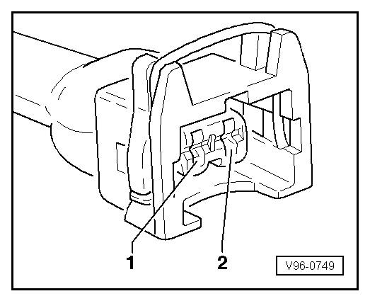
Test the following wiring connections for open circuits and short to positive or earth.

Connector for intake manifold change-over
Socket

Test box V.A.G 1598/31 Socket

2

104

  • Resistance in wiring: max. 1.5 ω

=> Current flow diagrams, Electrical fault finding and Fitting locations binder

  • ‒ If the wiring is OK, fit a new engine control unit
    .
  • ‒ Test operation of intake manifold change-over valve -N156 again
    .

Testing vacuum system > < Testing operation