audi Workshop Repair Guides

Audi Workshop Service and Repair Manuals

Testing electronic engine power control (electronic throttle) > < Testing secondary air inlet valve -N112
Motronic injection and ignition system (4-cyl.)
Testing secondary air inlet valve -N112
Testing secondary air pump relay -J299
 
A97-0025

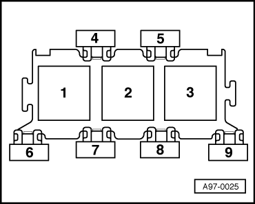
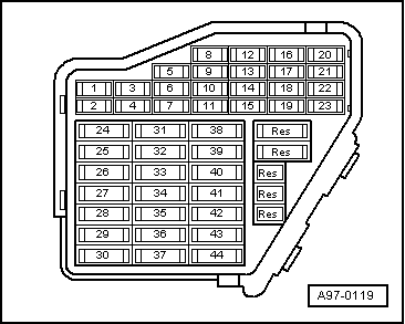
→ The secondary air pump relay is located in the electronics box in the plenum chamber, relay position 2.

Secondary air pump motor -V101 is located on the longitudinal member (right side).

  • ‒ Start final control diagnosis and activate secondary air pump relay -J299
    .
    • ‒ → The secondary air pump relay should pick up and secondary air pump motor -V101 should run intermittently.

A - If the relay does not pick up:

  • ‒ Test voltage supply of secondary air pump relay.
  • ‒ Test activation of secondary air pump relay.

B - If the relay picks up but the secondary air pump motor does not run:

  • ‒ Test voltage supply of secondary air pump motor.

Testing voltage supply of secondary air pump relay

 
A24-0298
  • ‒ Disconnect secondary air pump relay.
  • ‒ → Connect hand-held multimeter (voltage test range) as follows:

3-way relay carrier (electronics box in plenum chamber) socket position 2:
contact

Test against

8

Engine earth

    • ‒ Specification: approx. battery voltage

If the specification is not obtained:

 
A97-0025
  • ‒ Carry out the following tests (marked with dots):
  • ● → Test fuse No. S130 (40 A) in 3-way relay carrier in electronics box, in plenum chamber, socket position 7
  • ● Test for open circuit in wiring from battery + (terminal 30) via fuse No. S130 to secondary air pump relay -J299 (located in socket position 2 of 3-way relay carrier in electronics box in plenum chamber.)

=> Current flow diagrams, Electrical fault finding and fitting locations binder

 
A24-0298
  • ‒ → Connect hand-held multimeter (voltage test range) as follows:

3-way relay carrier (electronics box in plenum chamber) socket position 2:
contact

Test against

4

Engine earth

  • ‒ Operate starter briefly.
    • ‒ Specification: approx. battery voltage

If the specification is not obtained:

  • ‒ Carry out the following tests (marked with dots):
 
A97-0119
  • ● → Test fuse No. S234 (in fuse box, socket 34).
  • ● Test for open circuit in wiring from secondary air pump relay -J299 (located in 3-way relay carrier in electronics box in plenum chamber) to fuel pump relay via fuse No. S234 (in fuse box, socket 34).

=> Current flow diagrams, Electrical fault finding and fitting locations binder

Testing activation of secondary air pump relay

  • ‒ Switch off ignition.
  • ‒ Disconnect secondary air pump relay.
 
A24-0298
  • ‒ → Connect voltage tester V.A.G 1527 B as follows:

3-way relay carrier (electronics box in plenum chamber) socket position 2:
contact

Test against

6

Engine earth

  • ‒ Start final control diagnosis and activate secondary air pump relay -J299
    .
    • ‒ The LED should flash.

If the LED does not flash:

  • ‒ Switch off ignition.
  • ‒ Connect test box V.A.G 1598/31 to wiring harness for engine control unit. Do not connect to the engine control unit itself.
    .
 
A24-0298
  • ‒ → Test for open circuit and short to positive or earth in the following wiring connections:

3-way relay carrier (electronics box in plenum chamber) socket position 2:
contact

Test box V.A.G 1598/31
socket

6

66

  • ‒ Rectify any open/short circuit as necessary.

If no fault is found:

  • ‒ Fit a new secondary air pump relay -J299.

Testing voltage supply to secondary air pump motor

  • ‒ Unplug connector from secondary air pump motor -V101.
  • ‒ Connect voltage tester V.A.G 1527 B between contacts 1 and 2.
  • ‒ Start final control diagnosis and activate secondary air pump relay -J299
    .
    • ‒ The LED should light up.

If the LED does not light up:

  • ‒ Carry out the following tests (marked with dots):
  • ● Test for open circuit in wiring from connector for secondary air pump motor -V101 to secondary air pump relay -J299 (located in 3-way relay carrier in electronics box in plenum chamber, socket position 2)

=> Current flow diagrams, Electrical fault finding and fitting locations binder

  • ● Test for open circuit in wiring from connector for secondary air pump motor -V101 to earth connection 1 in engine compartment harness

=> Current flow diagrams, Electrical fault finding and fitting locations binder

If no fault is found:

  • ‒ Renew secondary air pump motor -V101.

Testing electronic engine power control (electronic throttle) > < Testing secondary air inlet valve -N112