audi Workshop Repair Guides

Audi Workshop Service and Repair Manuals

Mixture preparation system, electronic inj.,Gas > < Reading off readiness code
Motronic injection and ignition system (4-cyl.)
Readiness code
Generating readiness code

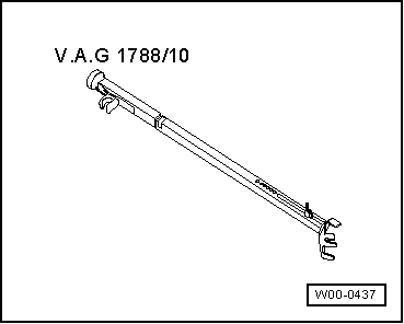
Special tools and workshop equipment required

 
W00-0437
  • ◆ Speed regulator V.A.G 1788/10

Test requirements

  • ● Engine not running
  • ● Electrical consumers switched off (radiator fan must not run during the test)
  • ● Coolant temperature at least 80°C

Work step 1: interrogate fault memory

  • ‒ Connect vehicle diagnostic, testing and information system VAS 5051 (or fault reader V.A.G 1551) and select engine electronics control unit by entering address word "01" ( .)
    When doing this the ignition must be switched on.
 
→ Indicated on display:
Rapid data transfer     HELP
Select function XX
  • ‒ Press keys 0 and 2 for the function "Interrogate fault memory" and confirm entry with Q key.
 
→ The number of faults stored or "No fault recognised!" will be shown on the display.
X Faults recognised!

If a fault is stored:

  • ‒ Rectify fault and erase fault memory. Then take vehicle for a road test and interrogate fault memory once again to check for faults.

If no faults are stored:

  • ‒ Press ⇒key.

Work step 2: erase fault memory

  • ● Ignition switched on.
 
→ Indicated on display:
Rapid data transfer     HELP
Select function XX
  • ‒ Press keys 0 and 5 for the function "Erase fault memory" and confirm entry with Q key.

Note:

If the fault memory is erased, the readiness code is set back and therefore has to be regenerated.

 
→ Indicated on display:
Rapid data transfer    ⇒
Fault memory is erased!
  • ‒ Press ⇒key.

The readiness code can be generated in two ways:

  • ● When the vehicle is driven under varying engine load conditions, the control unit carries out tests on the relevant parts of the emission control system, and in this way the readiness code is generated automatically.

or

  • ● Generate the readiness code as follows:

Work step 3: diagnosis of fuel tank breather valve

Test conditions

  • ● Engine idling
  • ● Coolant temperature above 85°C (Display group 4, display zone 3)
 
→ Indicated on display:
Rapid data transfer    HELP
Select function XX
  • ‒ Press keys 0 and 4 for function "Basic setting" and confirm entry by pressing Q.
 
→ Indicated on display:
Introduction of basic setting    Q
Enter display group number XXX
  • ‒ Enter "070" for Display Group 070 and confirm entry with Q key.
 
→ Indicated on display:
System in basic setting 70    ⇒
    1    2    3    4
  • ‒ Check the readout in display zone 4:

Display zones

1

2

3

4

Display Group 070: Diagnosis of fuel tank breather valve

Display

xx %

xx.x %

---

Indicates

Fuel tank breather valve:
degree of opening

Lambda control variation

Relative mass flow through tank breather valve

Diagnosis status

Range

min.: 0 %
max.: 100 %

min.: -25.0 %
max.: 25.0 %

Test OFF
Test ON
TBV OK
TBV n. OK
Abort

Specification

xx %

-2.5...2.5 %

xx...xx %

TBV OK

Note

If "TBV n. OK" appears on display, interrogate fault memory (=> Page 24-131.

If the specification "TBV O.K." is attained:

  • ‒ Press C key.

Work step 4: diagnosis of fuel supply system

  • ● Engine idling
  • ● Lambda control function active
 
→ Indicated on display:
Introduction of basic setting    Q
Enter display group number XXX
  • ‒ Enter "107" for "Display group number 107" and confirm with Q key.
 
→ Indicated on display
System in basic setting    107    ⇒
    1    2    3    4
  • ‒ Check the readout in display zone 4:

Display zones

1

2

3

4

Display Group 107: Diagnosis of fuel supply system

Display

xxx rpm

x.x %

Test ON

Indicates

rpm (actual)

Lambda control mean value (bank 1)

Diagnosis status

Range

min.: 550 rpm
max.: 7200rpm

-25.0 ... 25.0 %

Test OFF
Test ON
Syst. OK
Syst. n. OK

Specification

600 ... 900 rpm

-23 %...23 %

Syst. OK

Note

If the display shows "Syst. n. OK", interrogate fault memory
=> Page 01-9.

If the specification "Syst. OK" is obtained in display zone 4:

  • ‒ Press C key.

Work step 5: diagnosis of lambda probe heating

 
→ Indicated on display:
Introduction of basic setting    Q
Enter display group number XXX
  • ‒ Enter "041" for "Display group number 041" and confirm with Q key.
 
→ Indicated on display
System in basic setting 41    ⇒
    1    2    3    4
  • ‒ Check readouts in display zones 1 and 3:

Note:

The readouts can be obtained more quickly by increasing engine speed.

Display zones

1

2

3

4

Display Group 41: Lambda probe heating (at idling speed)

Display

xxx kOhm

Htg.bC.ON

xxx kOhm

Htg.aC.ON

Indicates

Bank 1, Probe 1

Status of heating

Bank 1, Probe 2

Status of heating

Range


Htg.bC.ON
Htg.bC.OFF

Htg.aC.ON
Htg.aC.OFF

Specification

less than 2 kOhm

Htg.bC.ON

less than 2 kOhm

Htg.aC.ON

Note

Important notes on Display group 41: display zones 1 and 3:

  • ◆ Display zones 1 and 3 remain blank until the lambda probes reach operating temperature (increase engine speed to obtain the readouts).
  • ◆ A resistance value below 0.9 kOhm should appear in display zones 1 and 3 when both lambda probes have reached operating temperature.
  • ◆ Do not continue the test until display zones 1 and 3 show a resistance value below 0.9 kOhm.
  • ‒ Press C key.

Work step 6: diagnose of ageing of lambda probe before catalytic converter

Test conditions

  • ● Increase engine speed until the exhaust temperature in display zone 2 reaches 200°C.
 
→ Indicated on display:
Introduction of basic setting    Q
Enter display group number XXX
  • ‒ Enter "034" for "Display group number 034" and confirm with Q key.
 
→ Indicated on display
System in basic setting    34    ⇒
    1    2    3    4
  • ‒ Check the readout in display zone 4:

Display zones

1

2

3

4

Display group 034: Ageing of lambda probe before catalytic converter

Display

xxxx rpm

xxx °C

x.x s

Test ON

Indicates

Engine speed

Exhaust temperature

Cycle duration of lambda probe (before catalytic converter)

Status of diagnosis

Range

min.: 550 rpm
max.: 7200rpm

70...850 °C

0.0...3.0 sec.

Test OFF
Test ON
B1-P1 OK
B1-P1 n. OK

Specification

600...900 rpm

above 200 °C

0.1...1.0 sec.

B1-P1 OK

Note

If "B1-P1 n. OK" appears on display: interrogate fault memory => Page 01-9.

If the specification "B1-P1 OK" is obtained in display zone 4:

  • ‒ Press C key.

Work step 7: diagnosis of condition of lambda probe after catalytic converter

  • ● Engine idling
 
→ Indicated on display:
Introduction of basic setting    Q
Enter display group number XXX
  • ‒ Enter "036" for "Display group number 036" and confirm with Q key.
 
→ Indicated on display
System in basic setting    36    ⇒
    1    2    3    4
  • ‒ Check the readout in display zone 2:

Display zones

1

2

3

4

Display group 036: Condition of lambda probe after catalytic converter

Display

x.xxx V

Test ON

Indicates

Voltage of lambda probe after catalytic converter bank 1

Status of diagnosis

Range

0.000V...1.000 Volt

Test OFF
Test ON
B1-P2 OK
B1-P2 n. OK


Specification

0.500...0.800 V

B1-P2 OK


Note

If "B1-P2 n. OK" appears on display: interrogate fault memory => Page 01-9.

If the specification is obtained:

B1-P2 OK in display zone 2

  • ‒ Press C key.

Work step 8: diagnosis of lambda control system

  • ● Engine idling
 
→ Indicated on display:
Introduction of basic setting    Q
Enter display group number XXX
  • ‒ Enter "037" for "Display group number 037" and confirm with Q key.
 
→ Indicated on display
System in basic setting    37    ⇒
    1    2    3    4
  • ‒ Check the readout in display zone 4:

Display zones

1

2

3

4

Display group 037: Lambda control system

Display

xx.x %

x.xxx V

xxx ms

Test ON

Indicates

Engine load

Voltage of lambda probe after catalytic converter

Lambda compensating value between
lambda probe 1 and lambda probe 2

Status of diagnosis

Range

0...175 %

0.000...1.000 Volt

---

Test OFF
Test ON
Syst. OK
Syst. n. OK

Specification

14...24 %

0.000...1.000 Volt

-800ms...800ms

Syst. OK

Note

If the display shows "Syst. n. OK", interrogate fault memory => Page 01-9.

If the specification "Syst. OK" is obtained in display zone 4:

  • ‒ Press C key.

Work step 9: diagnosis of catalytic converter

 
→ Indicated on display:
Introduction of basic setting    Q
Enter display group number XXX
  • ‒ Enter "046" for "Display group 046" and confirm entry with Q key.
 
→ Indicated on display:
System in basic setting 46    ⇒
    1    2    3    4
  • ● Increase engine speed to approx. 3000 rpm until the exhaust temperature (display zone 2) reaches 550°C.
  • ‒ Check the readout in display zone 4:

Note:

The diagnostic test of the catalytic converter takes approx. 60 seconds.

Display zones

1

2

3

4

Display group 046: Diagnosis of catalytic converter (bank 1)

Display

xxxx rpm

xxx °C

x.x s

---

Indicates

Engine speed

Exhaust temperature

Catalytic converter: conversion

Status of diagnosis

Range

min.: 550 rpm
max.: 7200rpm

70...850 °C

0.0...1.0 sec.

Test OFF
Test ON
Cat B1 OK
Cat B1 n. OK

Specification

1800..2200 rpm

400 ... 600°C

0.0...0.09 sec.

Cat B1 OK

Note

If "Cat B1 n. OK" appears on display, interrogate fault memory => Page 01-9. If there is no fault stored in fault memory, replace catalytic converter.

If the specification "Cat B1 OK" is obtained in display zone 4 :

  • ‒ Press C key.

Work step 10: diagnosis of secondary air system

 
→ Indicated on display:
Introduction of basic setting    Q
Enter display group number XXX
  • ‒ Enter "077" for Display group 077 and confirm entry with Q key.
 
→ Indicated on display:
System in basic setting 77    ⇒
    1    2    3    4
  • ‒ Check the readout in display zone 4:

Note:

The diagnostic test of the secondary air system takes approx. 60 seconds.

Display zones

1

2

3

4

Display group 077: Diagnosis of secondary air system

Display

xxxx rpm

xx.x g/s

xx %

Test ON

Indicates

Engine speed

Air mass

Percentage variation from specified value for secondary air system

Status of diagnosis

Range

min.: 550 rpm
max.: 7200rpm

Test OFF
Test ON
Syst. OK
Syst. n. OK
Abort

Specification

600...900 rpm

2.5 ... 4.5 g/s

-40 %...40 %

Syst. OK

Note

If the display shows "Syst. n. OK", interrogate fault memory => Page 01-9.

If the specification "Syst. OK" is obtained in display zone 4:

  • ‒ Press⇒key.

Work step 11: reading off readiness code.

  • ‒ Read off the readiness code () once again as an additional check.

Mixture preparation system, electronic inj.,Gas > < Reading off readiness code