audi Workshop Repair Guides

Audi Workshop Service and Repair Manuals

Dismantling and assembling air cleaner > < Technical data
Motronic injection and ignition system (4-cyl. turbo)
Servicing Motronic injection system
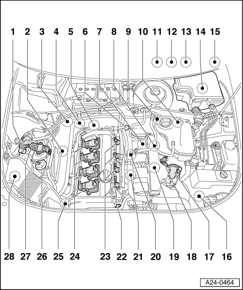
Fitting locations overview
 
A24-0464
  • Activated charcoal filter solenoid valve 1 -N80
    • ◆ Testing
  • Lambda probe (before catalytic converter) -G39 - 55Nm
    • ◆ Checking lambda probe heating before catalytic converter
    • ◆ Checking lambda probe and lambda control before catalytic converter
      => Page 24-72
    • ◆ Testing lambda probe ageing on lambda probe (before catalytic converter) => Page 24-85
    • ◆ Removing and installing
      => Page 24-106
 
A24-0464
  • Lambda probe (after catalytic converter) -G130 - 55 Nm
    • ◆ Testing lambda probe heating for lambda probe (after catalytic converter) => Page 24-100
    • ◆ Checking lambda probe and lambda control after catalytic converter
      => Page 24-89
    • ◆ Removing and installing
      => Page 24-106
  • Combination valve for secondary air system
    • ◆ Only with engine code ANB
    • ◆ Testing, removing and installing

=> 4-Cylinder engine (5-valve turbo), Mechanics; Repair group 26; Secondary air system; Removing and installing parts of secondary air system

  • Coolant temperature sender -G62
    • ◆ Testing
 
A24-0464
  • Fuel pressure regulator
  • Engine speed sender -G28
  • Secondary air inlet valve
    -N112
    • ◆ Only with engine code ANB
    • ◆ Fitting location=>Fig. 24-16
    • ◆ Testing
    • ◆ Green connector
  • 4 pin connector
    • ◆ Qty. 2
    • ◆ For lambda probe (before catalytic converter) -G39 and lambda probe heating -Z19 (black)
    • ◆ For lambda probe (after catalytic converter) -G130 and lambda probe heating -Z29 (brown)
    • ◆ Fitting location
      => Fig.24-14
 
A24-0464
  • 3 pin connector
    • ◆ Qty. 3
    • ◆ Fitting location
      => Fig.24-14
    • ◆ For knock sensor 1 -G61 (green)
    • ◆ For engine speed sender -G28 (grey)
    • ◆ For knock sensor 2 -G66 (blue)
  • Electronic throttle control warning lamp -K132
    • ◆ EPC warning lamp
    • ◆ Fitting location
      => Fig.24-15
  • Accelerator position sender -G79 and accelerator position sender 2 -G185
    • ◆ Fitting location
      => Fig.24-14
    • ◆ Testing
    • ◆ "Learning" kickdown function
 
A24-0464
  • Brake light switch -F and brake pedal switch -F47
    • ◆ Fitting location
      => Fig.24-15
  • Electronics box in plenum chamber
    • ◆ Fitting locations
      =>Fig. 24-16
    • ◆ Fitting location of engine control unit -J220 with integrated altitude sender -F96
    • ◆ Testing voltage supply of engine control unit
    • ◆ Procedure after voltage supply open circuit => Page 24-23
    • ◆ Replacing engine control unit => Page 24-24
 
A24-0464
    • ◆ Fitting location of secondary air pump relay -J299 (engine code ANB only)
    • ◆ Testing secondary air pump relay -J299:

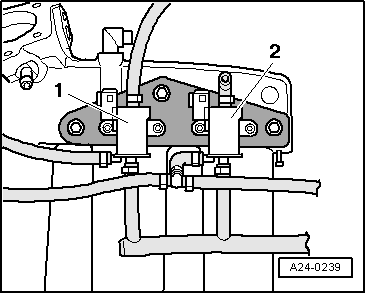
=> 4-Cylinder engine (5-valve turbo), Mechanics; Repair group 26; Testing secondary air system

    • ◆ Fitting location of Motronic current supply relay -J271 (engine code ANB from model year 2000 only)
    • ◆ Testing Motronic current supply relay -J271
    • ◆ Fitting location of fuse -S130 for secondary air pump -V101 (engine code ANB only)
  • Clutch pedal switch -F36
    • ◆ Fitting location
      => Fig.24-15
 
A24-0464
  • Charge pressure sender -G31
    • ◆ Fitting location
      =>Fig.24-17
    • ◆ Checking:

=> 4-Cylinder engine (5-valve turbo), Mechanics; Repair group 21; Charge air system with turbocharger; Testing charge pressure sender -G31

  • Throttle valve control part -J338
    • ◆ With throttle valve drive -G186, angle sender for throttle valve drive -G187 and angle sender 2 for throttle valve drive -G188
  • Intake air temperature sender -G42
    • ◆ Testing
 
A24-0464
  • Air recirculation valve for
    turbocharger -N249
    • ◆ Fitting location => Fig.24-16
    • ◆ Blue connector
  • Knock sensor 1 -G61
  • Knock sensor 2 -G66
  • Hall sender -G163
  • Injector -N30...-N33
  • Ignition coils -N, -N128, -N158, -N163
  • Solenoid valve for charge pressure control -N75
    • ◆ Checking:

=> 4-Cylinder engine (5-valve turbo), Mechanics; Repair group 21; Testing charge air system with turbocharger and charge pressure control valve

 
A24-0464
  • Air mass meter -G70
  • Output stage -N122
    • ◆ Testing
  • Secondary air pump motor -V101
    • ◆ Only with engine code ANB
    • ◆ Checking:

=> 4-Cylinder engine (5-valve turbo), Mechanics; Repair group 26; Secondary air system; Removing and installing parts of secondary air system

 
A24-0240

→ Fig.1    Fitting location of connectors

The following connectors are located underneath the coolant expansion tank:

  •     1 -    For lambda probe 2, (after catalytic converter) and heating (brown) - only on engines with engine code ANB.
  •     2 -    For lambda probe 1, (before catalytic converter) and heating (black)
  •     3 -    For engine speed sender -G28 (grey)
  •     4 -    For knock sensor 2 -G66 (blue)
  •     5 -    For knock sensor 1 -G61 (green)
 
A24-0204

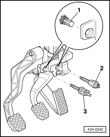
→ Fig.2    Fitting location of accelerator position senders -G79 and -G185

 
A24-0243

→ Fig.3    Fitting location of brake light switch -F, brake pedal switch -F47 and clutch pedal switch -F36

  •     1 -    Clip
  •     2 -    Clutch pedal switch -F36
  •     3 -    Brake light switch -F, Brake pedal switch -F47

Note:

To ensure a secure fitting, the switches may be installed only once.

Adjusting switch:

=> Brake system; Repair group 46

 
A24-0143

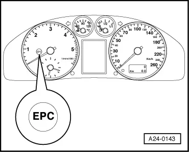
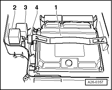
→ Fig.4    Fitting location of electronic throttle control warning lamp -K132

 
A24-0239

→ Fig.5    Fitting location of secondary air inlet valve -N112 and air recirculation valve for turbocharger -N249

  • ◆ Fitting location: underneath intake manifold
  •     1 -    Air recirculation valve for turbocharger -N249
  •     2 -    Secondary air inlet valve -N112

Note:

Illustration shows removed intake manifold from below.

 
A26-0357

→ Fig.6    Fitting locations of components in electronics box in plenum chamber

  •     1 -    Engine control unit
  •     2 -    Secondary air pump relay -J299
  •     3 -    Motronic current supply relay -J271
  •     4 -    Fuse -S130 for secondary air pump
 
A21-0167

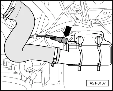
→ Fig.7    Fitting location ofcharge pressure sender -G31

Charge pressure sender -G31 -arrow- is installed at top of charge air cooler.

Dismantling and assembling air cleaner > < Technical data