audi Workshop Repair Guides

Audi Workshop Service and Repair Manuals

Mixture preparation system, electronic inj.,Gas > < Reading off readiness code
Motronic injection and ignition system (4-cyl. turbo)
Readiness code
Generating readiness code
 
W00-0437

Special tools and workshop equipment required

  • ◆ Speed regulator V.A.G 1788/10

Requirements:

  • ● Vehicle is stationary
  • ● Electrical consumers switched off (radiator fan must not run during the test)

Work sequence

  • ‒ Connect the vehicle diagnostic, test and information system VAS 5051 (or fault reader V.A.G 1551) and select engine electronics control unit by entering address word "01" .

Work step 1: interrogate fault memory

  • ● Ignition switched on.
 
→ Indicated on display:
Rapid data transfer     HELP
Select function XX
  • ‒ Press keys 0 and 2 for the function "Interrogate fault memory" and confirm entry with Q key.
 
→ The number of faults stored or "No fault recognised!" will be shown on the display.
X Faults recognised!

If a fault is stored:

  • ‒ Rectify fault and erase fault memory. Then take vehicle for a road test and interrogate fault memory once again to check for faults.

If no faults are stored:

  • ‒ Press ⇒key.

Work step 2: erase fault memory

  • ● Ignition switched on.
 
→ Indicated on display:
Rapid data transfer     HELP
Select function XX
  • ‒ Press keys 0 and 5 for the function "Erase fault memory" and confirm entry with Q key.

Note:

If the fault memory is erased, the readiness code is set back and therefore has to be regenerated.

 
→ Indicated on display:
Rapid data transfer    ⇒
Fault memory is erased!
  • ‒ Press ⇒key.

Work step 3: adjust the throttle valve control part to the engine control unit

  • ● Ignition switched on.
 
→ Indicated on display:
Rapid data transfer     HELP
Select function XX
  • ‒ Enter "04" to select "Basic setting" and confirm with Q key.
 
→ Indicated on display:
Introduction of basic setting    Q
Enter display group number XXX
  • ‒ Enter "060" for Display Group 060 and confirm entry with Q key.
 
→ Indicated on display:
System in basic setting 60    ⇒
    1    2    3    4
  • ‒ Check the specifications in display zone 3 and 4:

Display zones

1

2

3

4

Display Group 060: Adaption of throttle valve control part

Display

xx %

xx %

x

---

Indicates

Throttle valve angle
(angle sender 1)

Throttle valve angle
(angle sender 2)

Learning stage counter

Adaption status

Range

0...8

ADP. runs
ADP. O.K.
ERROR

Specification

3...93 %

97...3 %

8

ADP O.K.

Note

During the adaption process the learning stage counter should reach "8". (Some of the digits may be skipped)

If display reads "ERROR", interrogate fault memory
=> Page 24-143.

If the specification "ADP O.K." is attained:

  • ‒ Press C key.

Work step 4: diagnosis of fuel tank breather system

  • ● Engine idling

Note:

After starting the engine, enter address word "01" to re-select the engine control unit if necessary, and enter "04" to select the function "Introduction of basic setting".

 
→ Indicated on display:
Introduction of basic setting    Q
Enter display group number XXX
  • ‒ Enter "070" for Display Group 070 and confirm entry with Q key.
 
→ Indicated on display:
System in basic setting 70    ⇒
    1    2    3    4
  • ‒ Check the specification in display zone 4:

Note:

If the test does not start or if the display jumps from "Test ON" to "Test OFF", press the accelerator briefly. The test will now be repeated.

Display zones

1

2

3

4

Display Group 070: Diagnosis of fuel tank breather valve

Display

xx %

xx.x %

---

Indicates

Fuel tank breather valve: amount of opening

Lambda control variation

Status of diagnosis

Range

0...99 %

-25.0 ... 25.0 %

Test OFF
Test ON
TBV O.K.
TBV n. O.K.

Specification

0...99 %

-7.0...7.0 %

TBV O.K.

Note

If "TBV n. O.K." appears on display, interrogate fault memory (=> Page 24-123.

If the specification "TBV O.K." is attained:

  • ‒ Press ⇒key.

Work step 5: check lambda control operation

  • ● Engine running between 1800 and 2200 rpm.

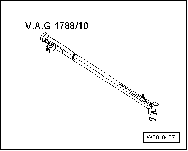
Note:

To obtain the higher engine speed specified above, use the speed regulator V.A.G 1788/10.

 
→ Indicated on display:
Rapid data transfer     HELP
Select function XX
  • ‒ Enter "08" to select the function "Read measured value block" and confirm entry with Q key.
 
→ Indicated on display:
Read measured value block    Q
Enter display group number XXX
  • ‒ Enter "030" to select Display Group 030 and confirm entry with Q key.
 
→ Indicated on display:
Read measured value block 30    ⇒
    1    2    3    4    
  • ‒ Check the readouts in display zones 1 and 2:

Note:

The readouts can be obtained more quickly by increasing engine speed.

Display zones

1

2

3

4

Display Group 030: Lambda probe status

Display

X X X

X X X

Indicates

Lambda probe status Bank 1, Probe 1

Lambda probe status
Bank 1, Probe 2

Range

0 = off
1 = on

0 = off
1 = on


Specification

1 1 1

1 1 0

Note

If the specification is not attained, interrogate fault memory => Page 01-9

Explanation of 3-figure displays in Display Group 030

X

X

X

Display zones 1 and 2

1

Lambda control active

1

Lambda probe condition

1

Status of lambda probe heating

Notes:

  • ◆ The lambda control function of the lambda probe (after catalytic converter; B1-P2) is inactive when the engine is not running under load
  • ◆ The first digit of the three-digit display (for heating) fluctuates between 0 and 1.

If the specifications are obtained:

  • ‒ Press ⇒key.

Work step 6: diagnosis of lambda probe ageing (cycle duration)

  • ● Engine still running between 1800 and 2200 rpm.
 
→ Indicated on display:
Rapid data transfer     HELP
Select function XX
  • ‒ Enter "04" to select "Basic setting" and confirm with Q key.
 
→ Indicated on display:
Introduction of basic setting    Q
Enter display group number XXX
  • ‒ Enter "034" for Display Group 034 and confirm entry with Q key.
 
→ Indicated on display:
System in basic setting 34    ⇒
    1    2    3    4
  • ‒ Check the readout in display zone 4:

Note:

It may take a few minutes before a diagnosis result is obtained.

Display zones

1

2

3

4

Display group 034: Diagnosis of lambda probe ageing

Display

xxxx rpm

xxx °C

x.x s

---

Indicates

Engine speed

Exhaust temperature

Cycle duration of lambda probe (before catalytic converter)

Status of diagnosis

Range

0...6800 rpm

70...850 °C

0.0...3.0 s

Test OFF
Test ON
B1-P1 O.K.
B1-P1 n. O.K.

Specification

1800...2200 rpm

Higher than 350 °C

0.0...1.0 s

B1-P1 O.K.

Note

If "B1-P1 n. O.K" appears on display: interrogate fault memory => Page 01-9.

If the specification "B1-P1 O.K." is attained:

  • ‒ Press ⇒key.

Work step 7: diagnosis of lambda control system

  • ● Engine still running between 1800 and 2200 rpm.
 
→ Indicated on display:
Introduction of basic setting    Q
Enter display group number XXX
  • ‒ Enter "037" for Display Group 037 and confirm entry with Q key.
 
→ Indicated on display:
System in basic setting 37    ⇒
    1    2    3    4
  • ‒ Check the readout in display zone 4:

Display zones

1

2

3

4

Display group 037: Diagnosis of lambda control system

Display

xxx %

x.xxx Volt

xxx ms

---

Indicates

Engine load

Lambda probe
voltage
Bank 1, Probe 2

Delay period of lambda control (before catalytic converter)
Bank 1

Status of diagnosis

Range

15...150 %

0.000...1.000 V

-800...800 ms

Test OFF
Test ON
SYST. O.K.
SYST. n. O.K.

Specification

15...25 %

0.100...0.900 V

-150...150 ms

SYST. O.K.

Note

If "SYST. n. O.K." appears on display: interrogate fault memory => Page 01-9.

If the specification "SYST. O.K." is attained:

  • ‒ Press ⇒key.

Work step 8: diagnosis of catalytic converter

  • ● Engine still running between 1800 and 2200 rpm.
 
→ Indicated on display:
Introduction of basic setting    Q
Enter display group number XXX
  • ‒ Enter "046" for Display Group 046 and confirm entry with Q key.
 
→ Indicated on display:
System in basic setting 46    ⇒
    1    2    3    4
  • ‒ Check the readout in display zone 4:

Note:

The diagnostic test of the catalytic converter takes approx. 60 seconds.

Display zones

1

2

3

4

Display group 046: Diagnosis of catalytic converter

Display

xxxx rpm

xxx °C

x.x s

---

Indicates

Engine speed

Exhaust temperature

Catalytic converter: conversion

Status of diagnosis

Range

0...6800 rpm

70...850 °C

0.0...1.0

Test OFF
Test ON
Cat B1 O.K.
Cat B1 n. O.K.

Specification

1800...2200 rpm

Higher than 350 °C

0.0...0.4

Cat B1 O.K.

Note

If "Cat B1 n. O.K." appears on display, interrogate fault memory (=> Page 01-9). If there is no fault stored in fault memory, replace catalytic converter.

If the specification "Cat B1 O.K. is attained:

  • ‒ Press ⇒key.

Work step 9: diagnosis of secondary air system

  • ● Engine still running between 1800...2200 rpm.
 
→ Indicated on display:
Introduction of basic setting    Q
Enter display group number XXX
  • ‒ Enter "077" for Display Group 077 and confirm entry with Q key.
 
→ Indicated on display:
System in basic setting 77    ⇒
    1    2    3    4
  • ‒ Check the readout in display zone 4:

Display zones

1

2

3

4

Display Group 077: Diagnosis of secondary air system

Display

xxxx rpm

xxx °C

xx.x g/s

---

Indicates

Engine speed

Coolant temperature

Air mass
Secondary air system

Status of diagnosis

Range

0...6800 rpm

-48...143 °C

0...20 g/s

Test OFF
Test ON
SYST. O.K.
SYST. n. O.K.

Specification

2000...2200 rpm

80...110 °C

5.0...10.0 g/s

SYST. O.K.

Note

The readout in display zone 3 appears only if the secondary air system is active (after a cold start or during diagnosis)

If "SYST. n. O.K." appears on display, interrogate fault memory => Page 01-9.

If the specification "SYST. O.K." is attained:

  • ‒ Press ⇒key.
 
→ Indicated on display (function selection):
Rapid data transfer    HELP
Select function XX

Work step 10: read off readiness code

  • ‒ Read off the readiness code => Page 01-55

Mixture preparation system, electronic inj.,Gas > < Reading off readiness code