audi Workshop Repair Guides

Audi Workshop Service and Repair Manuals

Motronic injection and ignition system (4-cyl.) > < Testing operation of camshaft timing control
Motronic injection and ignition system (6-cylinder)
Testing camshaft timing control
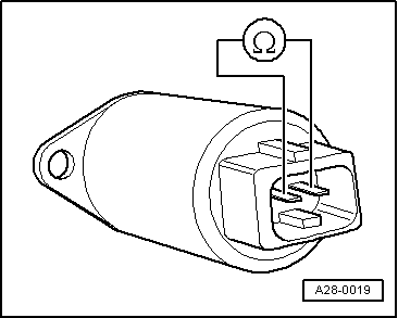
Testing solenoid valves for camshaft adjustment

Note:

Fitting locations of solenoid valves=>Pages 24-8.

Special tools, testers and auxiliary items

  • ◆ Hand multimeter V.A.G 1526 or V.A.G 1526 A
  • ◆ Diode test lamp V.A.G 1527
  • ◆ Adapter set V.A.G 1594
  • ◆ Test box V.A.G 1598/22
  • ‒ Connect fault reader V.A.G 1551
    .
  • ‒ Switch ignition on.
  • ‒ Start final control diagnosis and select camshaft timing control => Page 01-79.
 
→ Indicated on display:
Final control diagnosis    ⇒
Camshaft timing control 1

When the camshaft timing control is activated the solenoid valves should click audibly.

If the valve does not click, switch off the ignition.

  • ‒ Unplug connector from the solenoid valve which is being tested.
 
A28-0019
  • ‒ → Measure the resistance between the solenoid valve contacts using V.A.G 1526.
    • ‒ Specification: 10 ... 18ω
  • ‒ If the value does not match the specification, fit a new solenoid valve.

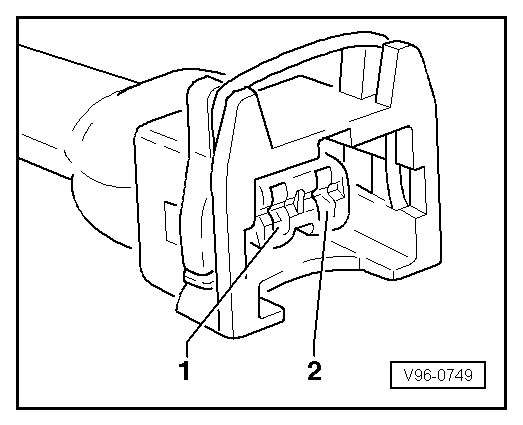
Testing voltage supply to camshaft adjustment valves

(-N205 and -N208)

  • ‒ Unplug connector on the solenoid valve which is being tested.
 
V96-0749
  • ‒ → Connect diode test lamp V.A.G 1527 to contact 1 on connector and to engine earth using auxiliary leads from V.A.G 1594.
  • ‒ Operate starter for a few seconds. The engine can be allowed to start.
  • Specification: The diode test lamp should light up.

If the diode test lamp does not light up, carry out the following tests:

  • ‒ Test fuse for camshaft adjustment valve.
  • ‒ Test for open circuit in wiring between contact 1 of connector for camshaft adjustment valve and fuse.

=> Current flow diagrams, Electrical fault-finding and Fitting locations

  • ‒ Test fuel pump relay and activation
    => Page 24-46.
 
V96-0749

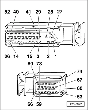
Testing activation of camshaft timing control

  • ‒ → Connect diode test lamp V.A.G 1527 to contact 1 (positive) and contact 2 on valve connector using test leads from auxiliary cable set V.A.G 1594.
  • ‒ Start final control diagnosis and select camshaft timing control => Page 01-79.

 
→ Indicated on display:
Final control diagnosis    ⇒
Camshaft timing control 1

When the camshaft timing control is activated the diode test lamp should start flashing.

  • ‒ If the diode test lamp does not flash or if it lights up continuously, connect test box V.A.G 1598/22 to wiring harness for engine control unit => Page 24-24.
 
A28-0022
  • ‒ → If the diode test lamp lights up continuously, test for short to earth in wiring from contact 2.

=> Current flow diagrams, Electrical fault-finding and Fitting locations

  • ‒ If the diode test lamp does not flash, test for open circuit or short to positive in wiring between contact 2 on connector and contact 55 on test box.

=> Current flow diagrams, Electrical fault-finding and Fitting locations

  • ‒ Rectify any short circuits to earth or open circuits if found.
  • ‒ If no short circuits or open circuits are found, fit a new engine control unit => Page 24-26.
  • ‒ If the wiring connections are OK, fit a new mechanical camshaft adjuster

=> 6-cylinder engine (5-valve), Mechanics; Repair group 15; Cylinder head, valve gear; Removing and installing camshafts

Motronic injection and ignition system (4-cyl.) > < Testing operation of camshaft timing control