Audi Workshop Service and Repair Manuals
HOME
FEATURES
MENU
INDEX
ABOUT US
Removing and installing parts of the injection system >
< Technical data
A4 Mk1
Power unit
Motronic injection and ignition system (6-cylinder)
Mixture preparation system, electronic inj.,Gas / Servicing Motronic injection system
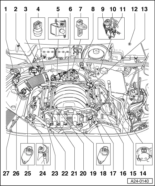
Fitting locations overview
Motronic injection and ignition system (6-cylinder)
Servicing Motronic injection system
Fitting locations overview
Diagnostic connector
◆
Located in rear ashtray in centre console
Fuel pump relay
◆
In relay position 6 in central electrics below dash panel
Activated charcoal filter solenoid valve 1 -N80
4 pin connector
◆
For Lambda probe 1 -G39
3 pin connector
◆
For knock sensor 1 -G61
Coolant temperature sender -G62
◆
On coolant pipe behind cylinder head Bank 1
Secondary air inlet valve
-N112
◆
Only on vehicles with secondary air system
Throttle valve control part -J338
Intake air temperature sender -G42
Intake manifold change-over valve -N156
4 pin connector
◆
For Lambda probe 2 -G108 and Lambda probe heating -Z28
3 pin connector
◆
For engine speed sender -G28
3 pin connector
◆
For knock sensor 2 -G66
Electronics box in plenum chamber
◆
Engine control unit -J220
◆
Secondary air pump relay -J299
(only on vehicles with secondary air system)
Fuel pressure regulator
Hall sender -G40
◆
Cylinder bank 2
Lambda probe 2 -G108
Engine speed sender -G28
◆
In gearbox housing above starter ring gear
Knock sensor 2 -G66
Camshaft adjustment valve 2 -N208
Ignition coils -N, -N128 and -N158
◆
With output stage -N122
Knock sensor 1 -G61
Injector -N30...-N33, -N83, -N84
Hall sender -G163
◆
Cylinder bank 1
Lambda probe 1 -G39
Earth connection
◆
On engine support, right
Camshaft adjustment valve 1
-N205
Air mass meter -G70
Secondary air pump motor -V101
Power unit
Motronic injection and ignition system (6-cylinder)
Mixture preparation system, electronic inj.,Gas / Servicing Motronic injection system
Fitting locations overview
Removing and installing parts of the injection system >
< Technical data