audi Workshop Repair Guides

Audi Workshop Service and Repair Manuals

Ignition system, glow plug system > < Testing angle senders for throttle valve drive
Motronic injection and ignition system (6-cylinder)
Testing electronic engine power control (electronic throttle)
Checking accelerator position senders
 
A24-0204

→ Fitting location of accelerator position sender -G79 and accelerator position sender 2 -G185

The accelerator pedal position senders -G79 and -G185 are located on accelerator pedal. Both senders inform the engine control unit of the driver's throttle requirement (pedal position) but function completely independently of each other (redundancy principle). Both are located in a single housing.

  • ‒ Connect vehicle diagnostic, testing and information system VAS 5051 (or fault reader V.A.G 1551) and select engine electronics control unit by entering address word "01" ( .)
    When doing this the ignition must be switched on.
 
→ Indicated on display:
Rapid data transfer     HELP
Select function XX
  • ‒ Enter "08" to select the function "Read measured value block" and confirm entry with Q key.
 
→ Indicated on display:
Read measured value block    Q
Enter display group number XXX
  • ‒ Enter "062" for Display Group 062 and confirm entry with Q key.
 
→ Indicated on display:
Read measured value block 62    ⇒
    1    2    3    4
  • ‒ Check display values for electronic throttle potentiometer voltages.

Display zones

1

2

3

4

Display Group 062: Electronic throttle potentiometer voltages

Display

xx %

xx %

xx %

xx %

Indicates

Throttle valve angle
(angle sender 1)

Throttle valve angle
(angle sender 2)

Accelerator position
sender

Accelerator position
sender 2

Range

min.: 0 %
max.: 100 %

min.: 0 %
max.: 100 %

min.: 0 %
max.: 100 %

min.: 0 %
max.: 100 %

Specification

3...93 %

97...3 %

12...97 %

4...49 %

Note:

The engine control unit converts the voltage readings from the angle senders into percentages of 5 V and displays them as percentages. (A supply voltage of 5 V is equivalent to 100%.)

  • ‒ Observe display zones 3 and 4.
  • ‒ Slowly depress accelerator to full throttle position.

The percentage value in display zone 3 should rise steadily between 12 and 97 % but without covering the full range of values.

The percentage value in display zone 4 should also rise steadily but without covering the full range of values (in this case 4...49 %).

Note:

The value shown in display zone 3 should always be about twice as high as the value shown in display zone 4.

If the display values do not appear as described:

  • ‒ Test voltage supply and wiring to accelerator position senders
    .
  • ‒ Adjust accelerator position senders (right-hand drive vehicles only).

=> Fuel supply system, Petrol engines; Repair group 20; Servicing accelerator linkage - right-hand drive vehicles

Testing voltage supply to accelerator position senders

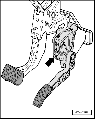
  • ‒ Remove storage compartment on driver's side.

=> General body repairs, Interior; Repair group 68; Storage compartments, covers and trim parts; Removing and installing driver's storage compartment

  • ‒ Unplug connector for accelerator position sender.

Left-hand drive vehicles

  • ‒ Switch ignition on.
 
A24-0209
  • ‒ → Connect multimeter (voltage measurement range) as follows:

Connector
Contact

Specification

1 + earth

approx. 5 V

1 + 5

approx. 5 V

2 + earth

approx. 5 V

2 + 3

approx. 5 V

Right-hand drive vehicles

  • ‒ Switch ignition on.
 
N23-0017
  • ‒ → Connect multimeter (voltage measurement range) as follows:

Connector
Contact

Specification

2 + earth

approx. 5 V

2 + 3

approx. 5 V

5 + earth

approx. 5 V

5 + 4

approx. 5 V

All models

If the specifications are obtained:

  • ‒ Test the signal wires.

If the specifications are not obtained:

  • ‒ Test wiring between engine control unit and accelerator position senders.

Testing wiring

  • ‒ Connect test box V.A.G 1598/31 to wiring harness for engine control unit. Do not connect to the engine control unit itself.
    => Page 24-21.

Left-hand drive vehicles

 
A24-0209
  • ‒ → Test for open circuit and short to positive or earth in the following wiring connections:

Connector
Contact

Test box V.A.G 1598/31
Socket

1

72

2

73

3

36

4

35

5

33

6

34

Right-hand drive vehicles

 
N23-0017
  • ‒ → Test for open circuit and short to positive or earth in the following wiring connections:

Connector
Contact

Test box V.A.G 1598/31
Socket

1

35

2

73

3

36

4

33

5

72

6

34

All models

  • ‒ Rectify any open/short circuit as necessary.

If no wiring fault is detected:

  • ‒ Renew accelerator position senders.

=> Fuel supply system, Petrol engines; Repair group 20; Servicing accelerator linkage - right-hand drive vehicles

Ignition system, glow plug system > < Testing angle senders for throttle valve drive