Motronic injection and ignition system (6 cyl. turbo)
Checking ignition system
Checking the intake air temperature sender
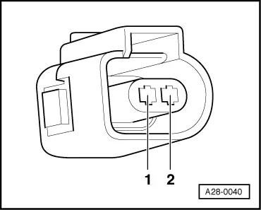
Fitting location of sender and connector
‒ Connect up vehicle diagnostic, testing and information system VAS 5051 or fault reader V.A.G 1551 and select engine electronics control unit with "Address word" 01 . For this purpose, the ignition must be switched on.
→ Display:
Rapid data transfer HELP
Select function XX
‒ Press keys 0 and 8 for the function "Read measured value block" and confirm entry with Q key.
→ Display:
Read measured value block HELP
Enter display group number XXX
‒ Press keys 0, 0 and 4 for "display group number 4" and confirm entry with Q key.
→ Indicated on display: (1...4 = display zones)
Read measured value block 4 ⇒
1 2 3 4
‒ Check specified result for intake air temperature sender (Display zone 4):
Display zones
1
2
3
4
Display group 4: Intake air temperature with engine idling
Display
xxxx rpm
xx.xxx Volt
xxx.x oC
xxx.x oC
Display
Engine speed
Battery voltage
Coolant temperature
Intake air temperature
Range
min.: 750 rpm max.: 7200 rpm
min.:10.000 Volt max.: 15.000 V
min.: - 48.0 oC max.: 143.0 oC
min.: - 48.0 oC max.: 143.0 oC
Specified value
xxxx rpm
12.000...15.000 volts
80.0...110.0 oC
Between ambient temperature and up to 120 oC 1)
1) If a temperature is displayed which deviates greatly from the ambient temperature of the sender, check sender and sender wiring for contact resistances and open circuit.
Checking wiring:
‒ Switch ignition off.
‒ Connect the V.A.G 1598/31 test box to wiring harness leading to engine control unit; the engine control unit should not be connected. .
‒ → Check wiring between test box and 2- pin connector for open circuit using current flow diagram. Specified result; max. 1.5 ω
Contact on 2-pin connector
Contact on control unit connector or test box
1 2
85 108
‒ Check the wiring for short circuit between Contact 1 and Contact 2 on 2-pin connector and for short to earth or positive.
If no wiring fault is detected:
Checking sender:
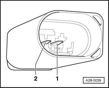
‒ → Measure resistance on connector to intake air temperature sender (G42) between contact 1 (signal) and contact 2 (earth).
Temperature oC
Resistance kω
-20
approx. 13.8
0
approx. 5.5
20
approx. 2.4
40
approx. 1.1
60
approx. 0.6
‒ If the value does not match specified value, fit a new intake air temperature sender.
‒ In order to renew the sender, the intake manifold must be removed => Page 24-16.