
A4 Mk1
|
Checking ignition system
Testing coolant temperature sender
Notes:
Test requirements:
Test sequence
|
| → When adjacent display appears: |
|
||
|
| → When adjacent display appears: |
|
||
|
| → Indicated on display: |
|
||||||||||||||||||||||||||||||
If display zone 3 shows an implausible value:
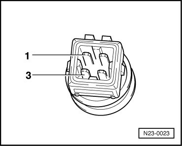
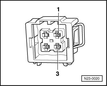
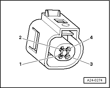
Coolant temperature sender with square plug: | |||||||||||||||||||||||||||||||
 |
|
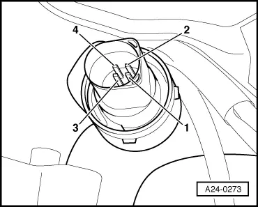
Coolant temperature sender with oval plug: |
 |
|
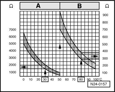
All models: Range A shows resistance values for temperature range 0...50 oC and range B the values for temperature range 50...100 oC. |
 |
|
|
→ Sample readings:
If specified value is not attained:
If specified value is attained:
|
 |
|||||||
|
Coolant temperature sender with square plug:
Coolant temperature sender with oval plug: |
 |
||||||
All models:
If no wiring fault is detected:
|