
A4 Mk1
|
Checking auxiliary signals
Testing data exchange between engine/ABS/gearbox control unit, dash panel insert
Notes:
Testing the bus system The test in principle is unaffected by the number of control units/systems connected to the databus. As an example the following test is conducted on three control units connected to the bus system. The fault table includes instructions to test the data exchange between engine control unit, gearbox control unit and ABS control unit.
=> Automatic gearbox; Repair group 01; Performing self-diagnosis
=> Running Gear FWD and 4WD; Repair group 01; Self-diagnosis; Electrical tests If a fault is displayed relating to "Data bus..." or "...communication":
|
 |
|
=> Current Flow Diagrams, Electrical Fault-Finding and Fitting Locations
If the communication between three or more control units takes place via a "two-line bus system", the following systematic procedure for fault-finding will be useful:
This helps to localise line faults. |
 |
|||||||||
|
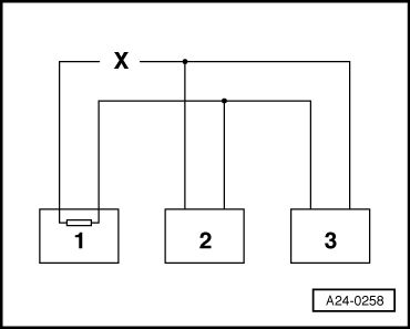
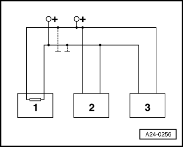
Example 1: The faults stored in the fault memories indicate that the control unit 1 does not communicate with control units 2 and 3.
=> Current Flow Diagrams, Electrical Fault-Finding and Fitting Locations
Example 2: |
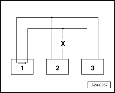 |
|||||||||
|
The faults stored in the fault memories indicate that the control unit 2 does not communicate with control units 1 and 3.
=> Current Flow Diagrams, Electrical Fault-Finding and Fitting Locations
Example 3: The faults stored in the fault memories indicate that sending or receiving operations are not possible in any of the control units. |
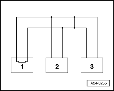 |
|||||||||
=> Current Flow Diagrams, Electrical Fault-Finding and Fitting Locations |
 |
|
If cause of fault "Data bus drive defective" cannot be found in bus lines check whether one of the control units is responsible for the fault. All the control units that communicate via the CAN data bus are still disconnected. The ignition is switched off.
|