audi Workshop Repair Guides

Audi Workshop Service and Repair Manuals

Learning kickdown function > < Checking angle sender for throttle valve actuator
Motronic injection and ignition system (6 cyl. turbo)
Checking electronic engine power control (electronic throttle)
Checking accelerator position sender
 
A24-0204

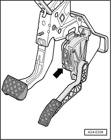
→ Installation position for gas pedal position sender -G79 and sender 2 for gas pedal position -G185

Both accelerator pedal position senders (G79 and G185) are located on the accelerator pedal and (completely independently) signal the driver's requirements to the engine control unit. Both senders are located in one housing.

  • ‒ Connect up vehicle diagnostic, testing and information system VAS 5051 or fault reader V.A.G 1551 and select engine electronics control unit with "Address word" 01 .
    For this purpose, the ignition must be switched on.
 
→ When adjacent display appears:
Rapid data transfer    HELP
Select function XX
  • ‒ Enter "08" to select the function "Reading measured value block" and confirm entry with Q key.
 
→ When adjacent display appears:
Reading measured value block    Q
Enter display group number XXX
  • ‒ Enter "062" for "display group number 062" and confirm entry with Q key.
 
→ Display:
Read measured value block 62    ⇒
    1    2    3    4
  • ‒ Check specified values for electronic throttle potentiometer voltages.

Display zones

1

2

3

4

Display group 062: Electronic throttle potentiometer voltages

Display

xx %

xx %

xx %

xx %

Display

Throttle valve angle
(angle sender 1)

Throttle valve angle
(angle sender 2)

Sender for
accelerator pedal position

Sender 2 for
accelerator pedal position

Range

min.: 0 %
max.: 100 %

min.: 0 %
max.: 100 %

min.: 0 %
max.: 100 %

min.: 0 %
max.: 100 %

Specified value

3...93 %

97...3 %

12...97 %
Idling speed value: 12...18 %

4...49 %
(Idling speed value: 4...13 %)

Note:

The engine control unit converts and displays the voltage readings from the angle senders as percentages of 5 V. (A 5 Volt supply corresponds to 100 %).

  • ‒ Observe readouts in display zones 3 and 4.
  • ‒ Slowly depress accelerator pedal.

Percentage displayed in zone 3 should rise evenly. The tolerance range from 12...97% is not fully utilised.

Percentage displayed in zone 4 should also rise evenly. The tolerance range from 4...49 % is not fully utilised.

Note:

The value displayed in zone 3 must always be about twice as large as that in zone 4.

If the displays are not as described:

  • ‒ Check voltage supply and wiring for accelerator position sender => Page 24-165.

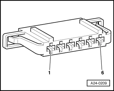
Checking voltage supply for accelerator position senders

  • ‒ Remove driver's storage compartment.

=> General Body Assembly - Interior; Repair Group 68; Dash panel; Removing driver's shelf

  • ‒ Detach connector from accelerator position senders.
  • ‒ Switch the ignition on.
 
A24-0209
  • ‒ → Connect multimeter as follows to measure voltage:

Connector
contact

Specified value

1 + earth

approx. 5 V

1 + 5

approx. 5 V

2 + earth

approx. 5 V

2 + 3

approx. 5 V

If specified values are attained:

  • ‒ Additionally check signal wires.

If specified values are not attained:

  • ‒ Check wiring between engine control unit and accelerator position senders.

Checking wiring

  • ‒ Connect the V.A.G 1598/31 test box to wiring harness leading to engine control unit; the engine control unit should not be connected=> Page 24-22.
 
A24-0209
  • ‒ → Check for open circuit and short to positive or earth in the following wiring connection:

Connector
contact

Test box V.A.G 1598/31
socket

1

72

2

73

3

36

4

35

5

33

6

34

  • ‒ Rectify any open/short circuit as necessary.

If no wiring fault is detected:

  • ‒ Replace accelerator position senders.

Note:

After replacement of accelerator position sender on vehicles with automatic/continuously variable gearbox, kickdown function must be learnt by engine control unit => Page 24-168.

Learning kickdown function > < Checking angle sender for throttle valve actuator