audi Workshop Repair Guides

Audi Workshop Service and Repair Manuals

Removing and installing intake manifold > < Technical data
Motronic injection and ignition system (6 cyl. turbo)
Servicing Motronic injection system
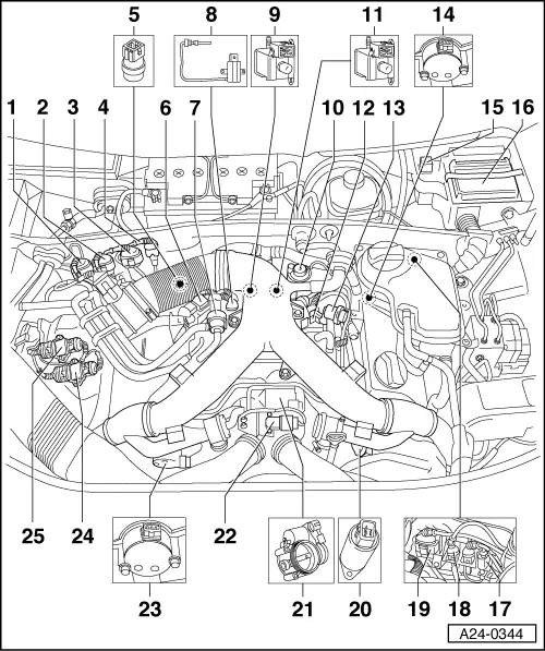
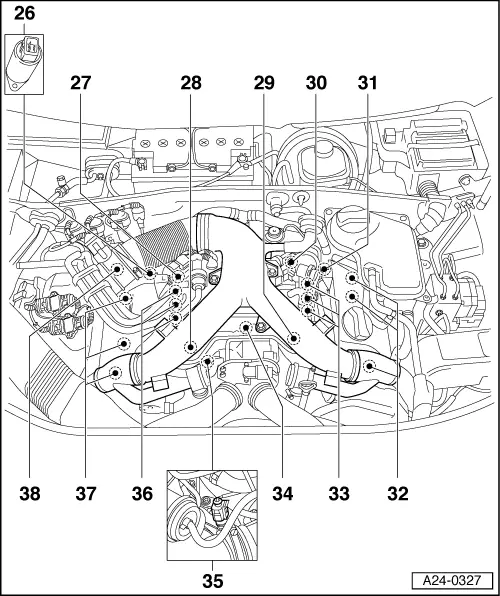
Fitting locations overview

Components A to H are not shown in the following exploded views.

  •     A -    Brake light switch (F) and brake pedal switch (F47)
    • ◆ in footwell on pedal bracket near brake pedal
  •     B -    Diagnosis plug
    • ◆ in rear ashtray on central console
  •     C -    Fuel pump relay
    • ◆ At relay position 4 of the central electronics beneath dash panel
  •     D -    Clutch pedal switch (F36)
    • ◆ in footwell on pedal bracket near brake pedal
  •     E -    Sender for accelerator position (G79) and sender 2 for accelerator position (G185)
    • ◆ in footwell on accelerator pedal (both senders are accommodated in one housing)
  •     F -    "EPC" warning lamp
    • ◆ in dash panel insert (significance of lamp
      =>Page 24-144.
  •     G -    Bank 1, lambda probe 2 -G130 with lambda probe heating -Z29
    • ◆ This lambda probe is accessible from below after raising vehicle.
  •     H -    Bank 2, lambda probe 2 -G131 with lambda probe heating -Z30
    • ◆ This lambda probe is accessible from below after raising vehicle.
 
A24-0344
  • Connector for bank 1, lambda probe 2 -G130 and lambda probe heating -Z29
    • ◆ 4-pin/green
  • Connector for bank 2, lambda probe 2 -G131 and lambda probe heating -Z30
    • ◆ 4-pin/brown
  • Connector for bank 1, lambda probe 1 -G39 and lambda probe heating -Z19
    • ◆ 4-pin/black
 
A24-0344
  • 3-pin connector
    • ◆ For knock sensor 1 (G61)
  • Coolant temperature sender (G62)
    • ◆ On coolant pipe behind cylinder head, bank 1
  • Solenoid valve for boost pressure control (N75)
  • Activated charcoal filter solenoid valve 1 (N80)
 
A24-0344
  • Exhaust gas temperature sender 1 (G235) and exhaust gas temperature sender 2 (G236)
    • ◆ Both senders are arranged one after the other; see also Page 24-15.
  • Intake air change-over valve -N335
  • Secondary air pump motor -V101
  • Checking secondary air inlet valve
    -N112
 
A24-0344
  • Air recirculation valve for turbocharger (N249)
  • Fuel pressure regulator
  • Hall sender (G40)
    • ◆ Cylinder bank 2
  • Secondary air pump relay (J299)
  • Engine control unit (J220)
  • 3-pin connector
    • ◆ For engine speed sender (G28)
    • ◆ Grey
  • 3-pin connector
    • ◆ For knock sensor 2 (G66)
  • Connector for bank 2, lambda probe 1 -G108 and lambda probe heating -Z28
    • ◆ 4-pin/black
 
A24-0344
  • Valve 2 for camshaft adjustment (N208)
  • Throttle valve control unit (J338)
    • ◆ With throttle valve drive (G186), angle sender for throttle valve drive (G187) and angle sender 2 for throttle valve drive (G188)
  • Boost pressure sender -G31
  • Hall sender (G163)
    • ◆ Cylinder bank 1
  • Final power stage 2 (N192)
    • ◆ For ignition coils, cylinder bank 2
  • Final power stage (N122)
    • ◆ For ignition coils, cylinder bank 1
 
A24-0327
  • Valve 1 for camshaft adjustment (N205)
  • Bank 1, lambda probe 1 -G39 with lambda probe heating
    -Z19
  • Knock sensor 1 (G61)
  • Knock sensor 2 (G66)
  • Engine speed sender (G28)
    • ◆ In gearbox casing above sender disc
  • Bank 2, lambda probe 1 -G108 with lambda probe heating
    -Z28
 
A24-0327
  • Ignition coils, cylinder bank 2
    • ◆ Cylinder 4 -N163
    • ◆ Cylinder 5 -N164
    • ◆ Cylinder 6 -N189
  • Injectors
    • ◆ Cylinder bank 2
      Cylinder 4 (N33)
      Cylinder 5 (N83)
      Cylinder 6 (N84)
  • Intake air temperature sender (G42)
    • ◆ Under the intake manifold at the front, near the throttle control unit
  • 2-pin connector
    • ◆ For intake air temperature sender (measurements to be carried out at this connector)
 
A24-0327
  • Injectors
    • ◆ Cylinder bank 1
      Cylinder 1 (N30)
      Cylinder 2 (N31)
      Cylinder 3 (N32)
  • Ignition coils, cylinder bank 1
    • ◆ Cylinder 1 -N
    • ◆ Cylinder 2 -N128
    • ◆ Cylinder 3 -N158
  • Air mass meter (G70)

Fitting location of exhaust gas temperature sender

 
A24-0328

→ Fig.1    Fitting location of exhaust gas temperature sender

-1--= Exhaust gas temperature sender -G235

-2- = Exhaust gas temperature sender -G236

Removing and installing intake manifold > < Technical data