audi Workshop Repair Guides

Audi Workshop Service and Repair Manuals

Procedure following interruption of voltage supply > < Removing and installing intake manifold
Motronic injection and ignition system (6 cyl. turbo)
Servicing Motronic injection system
Wiring and component check with test box V.A.G 1598/31

Notes:

  • ◆ The test box V.A.G 1598/31 is designed in such a way that it can be connected simultaneously to the engine control unit wiring harness and to the engine control unit itself.
  • ◆ This has the advantage that the electronic motor control system remains fully functional when the test box is connected (for example, for measuring signals when the engine is running).
  • ◆ Whether the engine control unit has to be additionally connected to the test box or not is described in the respective test procedures.
  • ◆ Always use adapter set V.A.G 1594 A for connecting up measuring instruments (e.g. voltage tester V.A.G 1527 B, hand-held multimeter V.A.G 1526 A etc.)
 
W00-0943

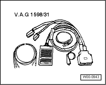
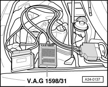
Special tools and workshop equipment required
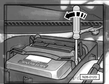
  • ◆ V.A.G 1598/31

Procedure

  • ‒ Switch ignition off.
  • ‒ Remove rubber seal from the front.
  • ‒ Detach plenum chamber cover to front.
  • ‒ Remove cover for electronics box in plenum chamber.

 
N28-0123
  • ‒ → Carefully lever off the retainer bar with a screwdriver -arrow-.
  • ‒ Release the connector latches and pull of the control unit connectors.
Important!
To prevent damage to the electronic components, select appropriate measuring range before connecting the measuring cables and observe the test requirements.
 
A24-0137
  • ‒ → Connect V.A.G 1598/31 test box to connector on wiring harness. The earth clip on the test box is to be connected to the battery negative. Whether or not the engine control unit has to be additionally connected to the test box is described in the respective test procedures.
  • ‒ Carry out test as described in the appropriate repair procedures.

Perform the following operations after re-connection of engine control unit:

  • ‒ Interrogate fault memory and erase, if necessary .
  • ‒ Perform adaptation of throttle valve control unit -J338 => Page 24-148.

Note:

In the first learning phase, during the basic setting operation for the engine, slightly irregular idling and slight jolting during driving are possible.

Procedure following interruption of voltage supply > < Removing and installing intake manifold