audi Workshop Repair Guides

Audi Workshop Service and Repair Manuals

Checking intake air system for leaks (non-metered air) > < Checking fuel pump relay -J17 and actuation
MPFI Fuel Injection and Ignition System
Repairing Multi Point Fuel Injection system
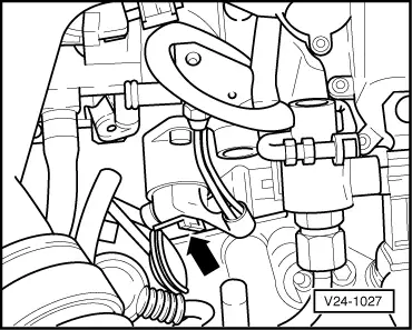
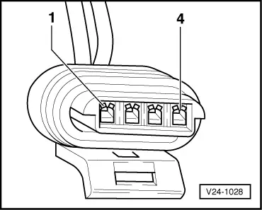
Checking idling stabilisation valve -N71
 
G24-0017

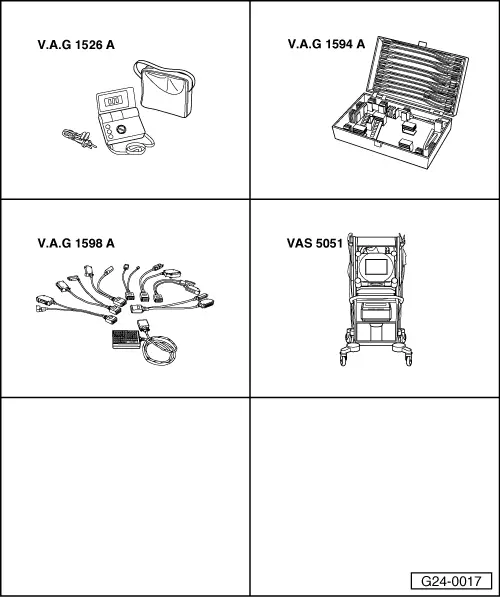
Special tools and workshop equipment required

  • ◆ V.A.G 1526 A
  • ◆ V.A.G 1594 A
  • ◆ V.A.G 1598 A
  • ◆ V.A.G 1598/12
  • ◆ VAS 5051 with VAS 5051/1
  • or
  • ◆ V.A.G 1551 with V.A.G 1551/3 A

Installation position => Installation position overview - Page 24-5

Notes:

  • ◆ After installing idling stabilisation valve, "Basic setting" function (display group 001) must be implemented to move valve to basic position .
  • ◆ After switching off ignition, engine control unit enters self-holding phase for 150 minutes. If repairs to idling stabilisation valve are performed during this period, a fault may be stored in the fault memory.
Attention:
Idling stabilisation valve is not to be removed and then moved to basic position as this could destroy it.
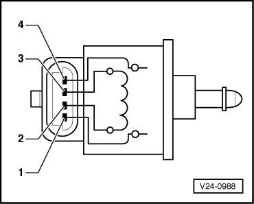
 
V24-1027

Mechanical checking

  • ‒ → Remove idling stabilisation valve -arrow-.
  • ‒ Attach connector to removed idling stabilisation valve
  • ‒ Switch on ignition.
    • ‒ Idling stabilisation valve must be retracted
  • ‒ Switch off ignition.
    • ‒ Idling stabilisation valve must be extended

If idling stabilisation valve does not react as described:

Checking internal resistance

  • ‒ Switch off ignition.
  • ‒ Pull connector off idling stabilisation valve.
 
V24-0988
  • ‒ → Connect multimeter between contacts 1 and 4 and 2 and 3 on valve to measure resistance.
    • ‒ Specification: 45 ... 60 ω

Note:

Resistance is in the lower tolerance range at ambient temperature and in the upper tolerance range when the engine is warm.

If a specification is not met:

  • ‒ Replace idling stabilisation valve.
 
A87-0016

If idling stabilisation valve is OK:

  • ‒ → With ignition switched off, use adapter V.A.G 1598/12 to connect test box V.A.G 1598 A to connector D only of engine control unit (control unit remains disconnected) => Page 24-9.

 
V24-1028
  • ‒ → Check for open circuit and short to earth/positive or earth in the following wiring connections:

Connector
Contact

Test box V.A.G 1598 A
Socket

1 (A)

2

2 (B)

10

3 (C)

11

4 (D)

3

  • ‒ Rectify any open/short circuit as necessary.

=> "Current Flow Diagrams, Electrical Fault Finding and Fitting Locations" binder

If no fault is found:

  • ‒ Replace engine control unit => Page 24-12.

Checking intake air system for leaks (non-metered air) > < Checking fuel pump relay -J17 and actuation