audi Workshop Repair Guides

Audi Workshop Service and Repair Manuals

#Diesel direct injection and glow #plug system (4-cyl.)>06.97 > < Checking the knock sensors
MPI fuel injection and ignition system
Checking ignition system
Checking Hall sender -G40
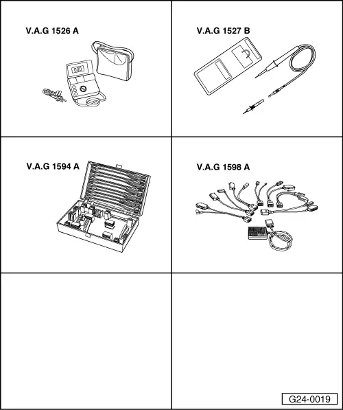
 
G24-0019

Special tools,
testers and equipment required

  • ◆ V.A.G 1526 A
  • ◆ V.A.G 1527 B
  • ◆ V.A.G 1594 A
  • ◆ V.A.G 1598 A
  • ◆ V.A.G 1598/11
 
V96-0836

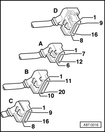
Fitting location => Fitting locations overview, Page 24-6

Checking power supply

  • ‒ Pull connector off Hall sender.
  • ‒ → Connect multimeter to contacts 1 (positive) and 3 (earth) to measure voltage.
  • ‒ Switch the ignition on.
    • ‒ Specification: min. 9 V

If the specification is not obtained:

 
A87-0016
  • ‒ → With the ignition switched off, use adapter V.A.G 1598/11 to connect test box V.A.G 1598 A to connector C only of engine control unit (control unit remains disconnected) .
 
V96-0836
  • ‒ → Check the following wires for open circuit and short to positive or earth (or short circuit to each other):

Connector
Contact

Measure against

Test box V.A.G 1598 A

1 (positive)

socket 7

3 (earth)

Engine earth

  • ‒ Rectify short circuit or open circuit if necessary.

=> "Current Flow Diagrams, Electrical Fault Finding and Fitting Locations" binder

  • ‒ If the wiring is OK, fit a new engine control unit => Page 24-20.

Checking operation

Note:

To check the operation of the Hall sender, unplug the 4-way connector from the output stage and interrogate fault memory after performing functional check.

Test requirements:

  • ● Power supply of Hall sender OK; checking => Page 28-40.
  • ‒ Slide back rubber grommets on connector for Hall sender but leave connector plugged in.
  • ‒ Connect up voltage tester V.A.G 1527 B between receptacle 2 (Hall sender signal) and receptacle 1 (positive).

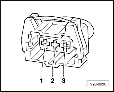
Note:

The connector contacts are numbered on the back of the connector.

  • ‒ Operate the starter for a few seconds.
 
A87-0016
    • ‒ The LED should flash briefly on alternate engine revolutions (i.e. once every two revolutions).

If the LED lamp does not flash:

  • ‒ Switch off ignition.
  • ‒ Pull connector off Hall sender.
  • ‒ → With the ignition switched off, use adapter V.A.G 1598/11 to connect test box V.A.G 1598 A to connector C only of engine control unit (control unit remains disconnected) => Page 24-17.
 
V96-0836
  • ‒ → Check for open circuit and short to earth/positive or earth in the following wiring connections:

Connector
Contact

Test box V.A.G 1598 A
Socket

2 (signal)

8

  • ‒ Rectify short circuit or open circuit if necessary.

=> "Current Flow Diagrams, Electrical Fault Finding and Fitting Locations" binder

  • ‒ If there are no open circuits or short circuits, reconnect engine control unit to engine wiring harness.
 
V96-0836
  • ‒ → Connect multimeter between contacts 2 and 3 to measure voltage.
  • ‒ Switch the ignition on.
    • ‒ Specification: min. 4 V

If the specification is not obtained:

  • ‒ Fit a new engine control unit => Page 24-20.

If the specification is obtained:

  • ‒ Fit a new Hall sender.

#Diesel direct injection and glow #plug system (4-cyl.)>06.97 > < Checking the knock sensors