audi Workshop Repair Guides

Audi Workshop Service and Repair Manuals

Checking change up/ change-down signal > < Checking gear signal
MPI fuel injection and ignition system
Checking auxiliary signals
Checking ignition timing retardation on changing gear
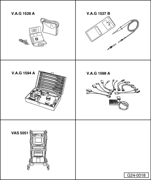
 
G24-0018

Special tools,
testers and equipment required

  • ◆ V.A.G 1526 A
  • ◆ V.A.G 1527 B
  • ◆ V.A.G 1594 A
  • ◆ V.A.G 1598 A
  • ◆ V.A.G 1598/11
  • ◆ VAS 5051 with VAS 5051/1
  • or
  • ◆ V.A.G 1551 with V.A.G 1551/3 A

Notes:

  • ◆ This signal causes the ignition timing to be briefly retarded during gearshifts to ensure a smoother gear change.
  • ◆ The wiring and gearshift signal are monitored by the gearbox control unit:

=> Automatic gearbox 01V Self-diagnosis; Repair Group 01; Interrogating fault memory

  • ◆ The following check is only to be performed if a gearshift fault has been stored in the automatic gearbox control unit.

Test requirements:

  • ● Control unit encoding OK .

Test sequence

Attention!
Secure fault reader to the rear seat and operate from this location. When doing this, always observe the relevant safety precautions.
Page 24-1.
  • ‒ Reading measured value block, display group 004, engine at idling speed .
 
→ Indicated on display:
Reading measured value block 4    ⇒
    1    2    3    4
  • ‒ Check display in display zone 4.
    • ‒ Specification: XXX X0
  • ‒ Take the vehicle for a test drive.
    • ‒ Gearshif specified value: XXX X1

If the displays are not as described:

 
A87-0016
  • ‒ → With the ignition switched off, use adapter V.A.G 1598/11 to connect test box V.A.G 1598 A to connector B and additionally to the engine control unit => Page 24-17.
  • ‒ Connect voltage tester V.A.G 1527 B as follows:

Test box V.A.G 1598 A
Socket

Measure against

33

Engine earth

  • ‒ Switch the ignition on.
    • ‒ The LED should light up.

If the LED does not light up:

  • ‒ Pull connector B off adapter V.A.G 1598/11.

If LED still does not light:

  • ‒ Fit a new engine control unit => Page 24-20.

If the LED then lights up:

  • ‒ Check the following wiring for short to earth:

Test box
V.A.G 1598 A
Socket

Control unit for
automatic gearbox
Contact

33

=> "Current Flow Diagrams, Electrical Fault Finding and Fitting Locations" binder

  • ‒ If wiring is OK, establish defect in automatic gearbox control unit.

If the LED lights up with connector B attached:

  • ‒ Reading measured value block, display group 004, engine at idling speed .
 
→ Indicated on display:
Reading measured value block 4    ⇒
    1    2    3    4
  • ‒ Check display in display zone 4.
  • ‒ Connect socket 33 of test box to engine earth for approx. 3 seconds.
    • ‒ Specification: XXX X1

If the display does not change:

  • ‒ Fit a new engine control unit => Page 24-20.

If the display changes:

  • ‒ Check for open circuit in the following wiring connections:

Test box
V.A.G 1598 A
Socket

Control unit for
automatic gearbox
Contact

33

=> "Current Flow Diagrams, Electrical Fault Finding and Fitting Locations" binder

  • ‒ If wiring is OK, establish defect in automatic gearbox control unit.

Checking change up/ change-down signal > < Checking gear signal