-
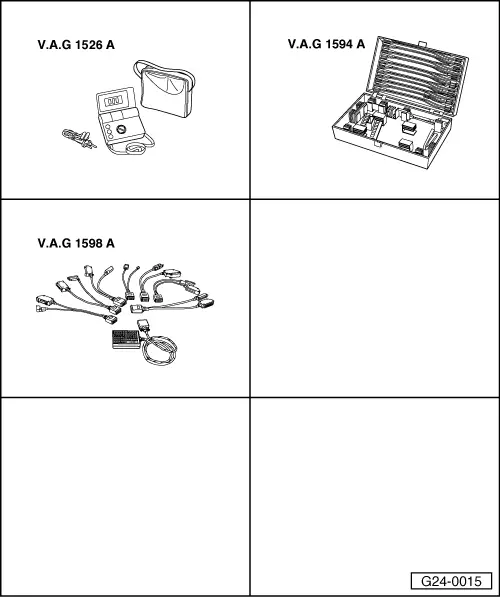
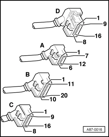
‒ → With the ignition switched off, use adapter V.A.G 1598/11 to connect test box V.A.G 1598 A to connector B and additionally to the engine control unit .
-
‒ Connect voltage tester V.A.G 1527 B as follows:
|
|
|---|
|
Test box V.A.G 1598 A
Socket
|
Measure against
|
|
28
|
Engine earth
|
-
‒ Switch the ignition on.
-
‒ The LED must light dimly and become brighter on pressing the accelerator pedal.
If the LED does not light up and does not become brighter:
-
‒ Check throttle valve potentiometer
.
-
‒ If the throttle valve potentiometer is OK, fit a new engine control unit => Page 24-20.
If the LED lights up and becomes brighter:
-
‒ Pull connector off automatic gearbox control unit.
-
‒ Check for open circuit and short to positive or earth in the following wiring connections:
|
|
|---|
|
Test box
V.A.G 1598 A
Socket
|
Control unit for
automatic gearbox
Contact
|
|
28
|
=> "Current Flow Diagrams, Electrical Fault Finding and Fitting Locations" binder
|
-
‒ If wiring is OK, establish defect in automatic gearbox control unit.
|