
A4 Mk1
|
Checking the fuel tank breather
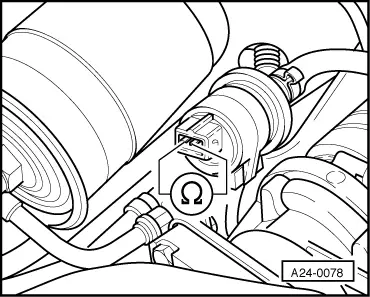
Checking ACF solenoid 1 -N80
Special tools,
Fitting location => Fitting locations overview, Page 24-6 Note: Checking operation=> Read measured value bloc display group 009, Page 01-129. Checking for leaks ACF solenoid valve -N80 remains closed when it is not receiving any current.
|
 |
|
|
Checking internal resistance
If the specification is not obtained:
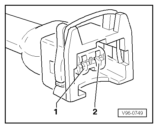
Checking power supply Note: The ACF valve receives its power supply via the fuel pump relay.
|
 |
|||||
If the LED does not light up:
|
 |
|
|
|
|
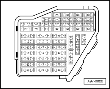
=> "Current Flow Diagrams, Electrical Fault Finding and Fitting Locations" binder
|
|
|
|
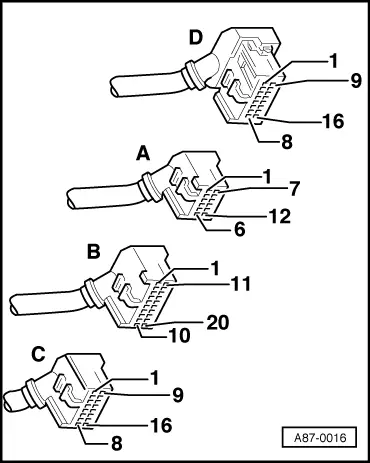
Checking actuation
If the LED lamp does not flash or if it lights up continuously: |
 |
|
|
|
|||||
=> "Current Flow Diagrams, Electrical Fault Finding and Fitting Locations" binder
|