audi Workshop Repair Guides

Audi Workshop Service and Repair Manuals

Renewing engine control unit > < Removing and installing throttle valve unit and intake manifold changeover system components
MPI fuel injection and ignition system
Servicing Multi Point Injection system
Checking wiring and components with test box V.A.G 1598 A

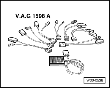
Special tools, testers and auxiliary items required

 
W00-0538
  • ◆ V.A.G 1598 A
  • ◆ V.A.G 1598/11
  • ◆ V.A.G 1598/12

Notes:

  • ◆ Test box V.A.G 1598 A must not be connected when performing diagnosis with fault reader V.A.G 1551.
  • ◆ Allow 30 seconds after switching off ignition before detaching or attaching connector of engine control unit.
Attention!
To prevent damage to the electronic components, switch to the respective measuring range before connecting the measuring cable and observe the test conditions.
  • ‒ Switch off ignition.
  • ‒ Remove engine control unit .
  • ‒ Release catches and detach connectors from control unit.
 
A87-0016
  • ‒ → Connect adapter cables V.A.G 1598/11 and V.A.G 1598/12 to detached connectors of engine control unit.

Notes:

  • ◆ For measurement purposes, connect test box V.A.G 1598 A to the respective adapter cable.
  • ◆ The contact assignment of connectors A and B with adapter cable V.A.G 1598/11 is not identical to the assignment of the sockets on the test box V.A.G 1598 A =>Pin assignment,
    Page 24-19.
  • ◆ The contact assignment of connector C with adapter cable V.A.G 1598/11 is identical to the assignment of the sockets on the test box V.A.G 1598 A.
  • ◆ The contact assignment of connector D with adapter cable V.A.G 1598/12 is identical to the assignment of the sockets on the test box V.A.G 1598 A.
  • ‒ Carry out test as described in the repair instructions.

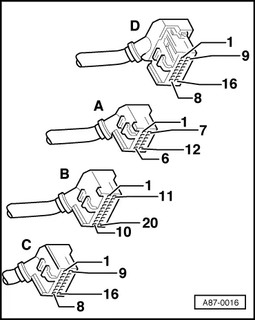
Pin assignment of test box V.A.G 1598 A with adapter cable V.A.G 1598/11

Connector A
Contact

V.A.G 1598 A Socket

Connector B
Contact

V.A.G 1598 A Socket

Connector B
Contact

V.A.G 1598 A Socket

1

41

1

21

13

33

2

42

2

22

14

34

3

43

3

23

15

35

4

44

4

24

16

36

5

45

5

25

17

37

6

46

6

26

18

38

7

47

7

27

19

39

8

48

8

28

20

40

9

49

9

29

10

50

10

30

11

51

11

31

12

52

12

32

Note:

The contact assignment of connectors C and D corresponds to the sockets on the test box V.A.G 1598 A.

Renewing engine control unit > < Removing and installing throttle valve unit and intake manifold changeover system components