|
Reading measured value block
Reading measured value block: display groups 000 to 010
|
Reading measured value block 0
|
⇒
|
◂ Indicated on display
|
|
|
|
1
|
2
|
3
|
4
|
5
|
6
|
7
|
8
|
9
|
10
|
◂ Display zones
|
Specification
|
Corresponds to
|
|
|
|
|
|
|
|
|
|
|
|
Learned value for throttle valve potentiometer
|
50...100
|
250...500 mV
|
|
|
|
|
|
|
|
|
|
|
Lambda learning demand
0 = Learning demand at idling speed and part throttle range
3 = Learning process completed at idling speed
|
3
|
|
|
|
|
|
|
|
|
|
|
Lambda control value )mean value 128/cylinder 1...3)
0 is displayed for vehicles with no lambda probes
|
120...136
|
|
|
|
|
|
|
|
|
|
Switching inputs
|
20
|
|
|
|
|
|
|
|
|
Idling stabilisation feedback (mean value 128)
|
126...130
|
|
|
|
|
|
|
|
Learned value for idling stabilisation, automatic gearbox with gear engaged (0 is displayed for manual gearbox)
|
0...10 or
236...255
|
|
|
|
|
|
|
Learned value for idling stabilisation, manual gearbox in idling position,
automatic gearbox in selector lever position P or N
|
0...14 or
240...255
|
|
|
|
|
|
Engine speed
|
26...30
|
650...750 rpm
|
|
|
|
Air mass meter output voltage
|
145...158
|
1.45...1.58 V
|
|
|
Coolant temperature
|
135...160
|
85...110°C
|
Notes on display group 000:
-
◆ If the values displayed do not correspond to the specified values, use the following display groups 001 - 023 for fault rectification.
-
◆ Do not deal with any deviations in display zone 8 until the lambda learning process at idling speed has been completed => display zone 9.
-
◆ If values greater than 3 are displayed in display zone 9 => Display group 007 or 008.
Display group 001; basic function
|
|
|
|
|
|
|
|
Reading measured value block 1
|
⇒
|
◂ Indicated on display
|
|
|
|
|
... °C
|
... V
|
-
|
... V
|
|
|
|
|
|
|
|
|
|
Engine control unit power supply
▪ 12.0 ... 14.0 V OK
|
|
|
|
|
|
|
|
Unallocated (only for vehicles with secondary air)
|
|
|
|
|
|
Air mass meter output voltage
▪ 1.450 ... 1.580 V OK (for new engines, max. 1.660 V)
▪ In the event of engine speed increase, display value rises to 2.500 V, drops to 0.000 V and starts rising again.
|
|
|
|
|
Coolant temperature
▪ 85 ... 110 °C OK.
|
|
|
|
|
|
|
|
Test table, display group 001
|
|
|---|
|
Display zone
|
Readout on V.A.G 1551
|
Cause of fault
|
Fault rectification
|
|
1
|
Less than
|
- Engine too cold
|
- Perform test drive if necessary
|
|
|
85 °C 1)
|
- Coolant temperature sender or wiring to engine control unit
|
- Interrogate fault memory
|
|
|
Greater than
|
- Radiator dirty
|
- Clean radiator
|
|
|
110°C 1)
|
- Radiator fan not working
|
- Check operation
|
|
|
|
- Thermostat defective
|
- Check coolant thermostat
|
|
|
|
- Coolant temperature sender or wiring to engine control unit
|
- Interrogate fault memory => Page 28-27
|
1) Vehicle at operating temperature.
Notes on display zone 1:
-
◆ The coolant temperature sender is a temperature-sensitive resistor. If the sender signal is biased, for example due to moisture in a connector (effect similar to parallel resistor), this biasing may be in a range which the fault memory is still not able to detect.
-
◆ If a fault has been stored relating to the coolant temperature sender, a coolant temperature of 20 °C is displayed in the measured value block when the engine is started. It will go up by 10°C for every minute of engine operation. The maximum substitute value is 85°C.
|
Display zone
|
Readout on V.A.G 1551
|
Cause of fault
|
Fault rectification
|
|
2
|
Less than
1.450 V
|
- Large quantity of unmetered air between intake manifold and air mass meter
|
- Eliminate air leak
|
|
|
Greater than
1.580 V
|
- Loads switched on, e.g. air conditioner is on; steering wheel is at end stop; selector lever of automatic gearbox not set to position "P" or "N"
|
- Switch off all electrical loads
Put steering wheel in its centre position
Move selector lever to "P" or "N"
|
Notes on display zone 2:
-
◆ Only assess the tolerance range of the air mass meter output voltage in function 04 "Basic setting" at idling speed.
-
◆ The air-mass meter output voltage decreases by 0.01 V for every 500 m above sea level.
|
|
|---|
|
Display zone
|
Readout on V.A.G 1551
|
Cause of fault
|
Fault rectification
|
|
4
|
Less than 12 V
|
- Alternator defective, battery heavily discharged
|
- Check voltage, charge battery
|
|
|
|
- High load on electrical system shortly after starting engine due to high charge current and load from ancillaries
|
- Increase engine speed for several minutes and switch off ancillaries
|
|
|
|
- Contact resistance in power supply or earth connection for engine control unit
|
- Check power supply to engine control unit => Page 28-31
|
|
|
|
- Current drain with ignition off
|
- Eliminate current drain
|
|
|
Greater than 14.0 V
|
- Voltage regulator on alternator defective
|
- Check voltage; if necessary, fit a new voltage regulator.
|
|
|
|
- Excess voltage from assisted start or high speed charging
|
- Interrogate fault memory
=> Page 01-10
|
Display group 002, throttle valve potentiometer:
|
|
|
|
|
|
|
|
Reading measured value block 2
|
⇒
|
◂ Indicated on display
|
|
|
|
|
... V
|
... V
|
... V
|
0
|
|
|
|
|
|
|
|
|
|
Idling switch
▪ 0 = open
▪ 1 = closed
|
|
|
|
|
|
|
Learned value for throttle valve potentiometer
▪ 0.250 ... 0.500 V OK
|
|
|
|
|
|
Throttle valve potentiometer voltage (idling speed to part throttle range)
▪ 0.250 ... 1.275 V OK
|
|
|
|
|
Throttle valve potentiometer voltage (idling speed to full throttle range)
▪ 0.250 ... 4.750 V OK
|
|
|
|
|
|
|
|
Test table, display group 002
|
|
|---|
|
Display zone
|
Readout on V.A.G 1551
|
Cause of fault
|
Fault rectification
|
|
1
|
Deviation from tolerance range
|
- Throttle valve potentiometer -G69 defective or incorrectly set
|
- Interrogate fault memory => Page 24-95 or => Display group 009, display zone 4
|
|
2
|
Outside
the tolerance range
|
- Throttle valve potentiometer -G69 defective or incorrectly set
|
- Interrogate fault memory => Page 24-95 or => Display group 009, display zone 4
|
|
3
|
Outside
the tolerance range
|
- Idling switch actuated or defective
- Throttle valve potentiometer -G69 defective or incorrectly set
|
- Interrogate fault memory => Page 24-95 or => Display group 009, display zone 4
|
|
|
|
- Loads switched on, e.g. air conditioner is on; steering wheel is at end stop; selector lever of automatic gearbox not set to position "P" or "N"
|
- Switch off all electrical loads
Put steering wheel in its centre position
Move selector lever to "P" or "N"
|
|
|
|
- Moisture in connector of throttle valve potentiometer -G69
|
- Check connector
|
|
|
|
- Earth point at intake manifold
|
- Check earth connection
=> "Current Flow Diagrams, Electrical Fault Finding and Fitting Locations" binder
|
Notes on display zone 3:
-
◆ Idling switch must be closed for checking throttle valve potentiometer learned value => Display zone 4.
-
◆ If the displays in zones 2 and 3 agree at idling speed, the learning process is OK. The last value learned is constantly displayed if no learning process takes place.
-
◆ The throttle valve potentiometer learned value is set to 0.550 V if the control unit is de-energised.
|
|
|---|
|
Display zone
|
Readout on V.A.G 1551
|
Cause of fault
|
Fault rectification
|
|
4
|
0 or 1
|
- -F60 idling switch defective
- Throttle valve potentiometer -G69 defective or incorrectly set
|
- Interrogate fault memory => Page 24-100
|
|
|
|
- Throttle valve sticking
- Floor mat pressing down on accelerator
|
- => Display group 011, Display zone 4
Rectify fault
|
|
|
|
- Moisture in connector of throttle valve potentiometer -G69
|
- Check connector
|
|
|
|
- Throttle cable setting
|
- Adjust throttle cable
|
Display group 003; basic function
|
|
|
|
|
|
|
|
Reading measured value block 3
|
⇒
|
◂ Indicated on display
|
|
|
|
|
rpm
|
...%
|
...%
|
... km/h
|
|
|
|
|
|
|
|
|
|
Speed
|
|
|
|
|
|
|
Throttle valve angle:
▪ Idle speed: 0% OK
▪ Full throttle: Greater than 95% OK
|
|
|
|
|
|
|
Engine load (idling speed)
▪ 15.0 ... 35.0% OK
|
|
|
|
|
|
Engine speed (idling speed)
▪ 650 ... 750 rpm OK
▪ 750 ... 850 rpm OK on vehicles with no air conditioner, heated rear windscreen switched on
|
|
|
|
|
|
|
|
Test table, Display group 003
|
|
|---|
|
Display zone
|
Readout on V.A.G 1551
|
Cause of fault
|
Fault rectification
|
|
1
|
Greater than 750 rpm
|
- Idling switch -F60 defective or incorrectly set
|
- Check and adjust idling speed switch -F60
=> Page 24-100 or => Display group 004, Display zone 4
|
|
|
|
- Air intake system drawing in large quantities
- of unmetered air
|
- Check air intake system for leaks
|
|
|
|
- Idle stabilisation valve -N71 is sticking or stiff
|
- Perform final control diagnosis
|
|
|
Less than 650 rpm
|
- Idle stabilisation valve -N71 is sticking or stiff
|
- Perform final control diagnosis
|
|
|
|
- Idling switch -F60 defective or incorrectly set
|
- Check and adjust idling speed switch -F60
=> Page 24-100 or => Display group 004, Display zone 4
|
|
|
|
- Loads switched on, e.g. air conditioner is on; steering wheel is at end stop; selector lever of automatic gearbox not set to position "P" or "N"
|
- Switch off all electrical loads
Put steering wheel in its centre position
Move selector lever to "P" or "N"
|
|
|
|---|
|
Display zone
|
Readout on V.A.G 1551
|
Cause of fault
|
Fault rectification
|
|
2
|
Outside
the tolerance range
|
- Poor idle (is not running on all cylinders)
|
- Injector or spark plugs defective
|
|
|
|
- Air mass meter -G70 defective
|
- Interrogate fault memory => Page 01-10 or => Display group 001, Display zone 2
|
|
|
|
- Idling stabilisation valve -N71 defective
|
- Interrogate fault memory or =>Display group 018
|
|
|
|
- Loads switched on, e.g. air conditioner is on; steering wheel is at end stop; selector lever of automatic gearbox not set to position "P" or "N"
|
- Switch off all electrical loads
Put steering wheel in its centre position
Move selector lever to "P" or "N"
|
Note on display zone 2:
Only assess engine load tolerance band at idling speed in function 04 "Basic setting"
|
|
|---|
|
Display zone
|
Readout on V.A.G 1551
|
Cause of fault
|
Fault rectification
|
|
3
|
Greater than 0% at idling speed
|
- -G69 throttle valve potentiometer defective
|
- Interrogate fault memory or =>Display group 002
|
|
|
|
- Throttle cable setting
|
- Adjust throttle cable
|
|
|
|
- Throttle valve sticking
|
- Rectify fault
|
|
|
Less than 95% at full throttle
|
- -G69 throttle valve potentiometer defective
|
- Interrogate fault memory or =>Display group 002
|
|
|
|
- Throttle cable setting
|
- Adjust throttle cable
|
|
|
|
- Throttle valve potentiometer -G69 incorrectly set
|
- Check throttle valve potentiometer -G69 => Page 24-95
|
Notes on display zone 3:
-
◆ For checking at full throttle, switch engine off and ignition on.
-
◆ Vehicles with manual and automatic gearbox have different throttle valve units. The start of the opening of the 2nd stage of the throttle valve unit can be measured with ignition switched on; this also checks that it has been fitted correctly. Manual gearbox 45... 53%; Automatic gearbox 27 ... 35%.
|
Display zone
|
Readout on V.A.G 1551
|
Cause of fault
|
Fault rectification
|
|
4
|
No
display
|
- Fault in wiring between dash panel insert and engine control unit
|
- Check wiring
=> "Current Flow Diagrams, Electrical Fault Finding and Fitting Locations" binder
|
|
|
|
- Open circuit or short circuit between speedometer sender/road speed sender -G22/-G68 and engine control unit
|
- Check wiring
=> "Current Flow Diagrams, Electrical Fault Finding and Fitting Locations" binder
|
|
|
|
- Speedometer sender/road speed sender -G22/-G68
|
- Check speedometer sender/road speed sender -G22/-G68 => Page 24-126
|
Note on display zone 4:
If vehicle speed is not displayed on V.A.G 1551, start by checking whether speedometer reading is OK. If not, check speedometer:
=> "Current Flow Diagrams, Electrical Fault Finding and Fitting Locations" binder
Display group 004: Idling stabilisation
|
|
|
|
|
|
|
|
|
|
|
|
|
|
|
|
Reading measured value block 4
|
|
|
|
|
|
|
|
|
◂ Indicated on display
|
|
|
|
|
1
|
4
|
0
|
|
0
|
0
|
1
|
|
1
|
0
|
|
|
|
|
|
|
|
|
|
|
X
|
X
|
X
|
|
X
|
X
|
|
▪ Heated rear window signal: 0 = off, 1 = on
▪ Display always 0 on vehicles with air conditioner
▪ Air conditioner compressor 0 = off, 1 = on
▪ Idle switch: 0 = open, 1 = closed
▪ Gear recognition signal: 1 = manual gearbox or automatic gearbox in selector lever position "P" or "N"
▪ 0 = automatic gearbox in selector lever position R, D, 4, 3, 2
▪ Gearbshift signal: 0 = not active, 1 = active
|
|
|
|
|
|
|
Idling stabilisation learned value for automatic gearbox (AT)
▪ In selector lever position D, 2, 3, 4 or R +10... -20 OK
▪ Display always 0 for manual gearbox (MT)
|
|
|
|
|
|
Learned value for idle stabilisation
▪ For manual gearbox (MT) in idling position +14... -16 OK
▪ (new engines +20... -16)
▪ For automatic gearbox (AT) in selector lever position "P" or "N" +10... -20 OK
▪ (new engines +16... -20)
|
|
|
|
|
Idling control at idle
▪ 0 ± 2 OK
|
|
|
|
|
|
|
Notes on display zones 2 and 3:
-
◆ Only assess values in display zone 2 or 3 if idling control is within tolerance at idle (display zone 1). If idling control is not within the tolerance after 1 minute waiting time, learning does not take place in display zone 2 or 3.
-
◆ Positive learned values indicate higher learned value than in basic setting: -N71 still open.
Negative learned values indicate lower learned value than in basic setting: -N71 is still closed.
Test table, Display group 004
|
|
|---|
|
Display zone
|
Readout on V.A.G 1551
|
Cause of fault
|
Fault rectification
|
|
1
|
Outside the
|
- Fault in fault memory
|
- Interrogate fault memory
|
|
|
tolerance
range
|
- Idling switch -F60 actuated or defective
|
- Check idling switch -F60 => Page 24-100 and => Display group 002, display zone 4
|
|
|
|
- Idling stabilisation valve -N71 defective
|
- Check idling stabilisation valve -N71 => Page 24-49.
|
|
|
|
- Loads switched on, e.g. air conditioner is on; steering wheel is at end stop; selector lever of automatic gearbox not set to position "P" or "N"
|
- Switch off all electrical loads
Put steering wheel in its centre position
Move selector lever to "P" or "N"
|
|
|
|
- Throttle valve sticking
- Floor mat pressing down on accelerator
- Unmetered air
|
- Rectify fault
|
|
|
|---|
|
Display zone
|
Readout on V.A.G 1551
|
Cause of fault
|
Fault rectification
|
|
2
|
Greater than +14 (MT)
|
- Idling stabilisation valve -N71 defective
|
- Check idling stabilisation valve -N71 => Page 24-49.
|
|
|
or
Greater than +10 (AT)
|
- Loads switched on, e.g. air conditioner is on; steering wheel is at end stop; selector lever of automatic gearbox not set to position "P" or "N"
|
- Switch off all electrical loads
Put steering wheel in its centre position
Move selector lever to "P" or "N"
|
|
|
|
- Suction jet pump clogged (automatic gearbox)
|
- Rectify fault
|
|
|
Less than -16 (MT)
|
- Idling stabilisation valve -N71 defective
|
- Interrogate fault memory or =>Display group 018
|
|
|
or
Less than -20
(AT)
|
- Large volume of unmetered air, intake manifold area, throttle valve stop not OK, leakage air at throttle valve 2nd stage
|
- Rectify fault
|
|
|
|---|
|
Display zone
|
Readout on V.A.G 1551
|
Cause of fault
|
Fault rectification
|
|
3
|
Outside the
tolerance
|
Vehicles with automatic gearbox only:
|
|
|
|
range
|
- Display zone 2 outside tolerance range
|
- => Display zone 2
|
|
|
|
- Display zone 2 within tolerance range
|
|
|
|
|
- Set selector lever to D and observe idling speed for approx. 1 min; if display zone 3 remains outside tolerance range, then the gearbox will not operate smoothly
|
- Check gearbox
|
|
4
|
Not
001 10
|
- Idling switch -F60 actuated or defective
|
- Check and adjust idling speed switch -F60
|
|
|
|
- A/C compressor switched on
|
- Switch off the air conditioner
|
|
|
|
- Air conditioner requires higher cooling or heat output ("high")
|
- Check air conditioner compressor shut-off
|
|
|
|
- Heated rear window on
|
- Switch off heated rear window
|
|
|
|
- Gear engaged (automatic gearbox)
|
- Move selector lever to "P" or "N"
|
Display group 005, lambda learned values, cylinder bank 1:
|
|
|
|
|
|
|
|
Reading measured value block 5
|
⇒
|
◂ Indicated on display
|
|
|
|
|
... %
|
... %
|
... %
|
... %
|
|
|
|
|
|
|
|
|
|
Lambda learned value, part throttle 3 (bank 1)
▪ -25% ... + 25% OK
|
|
|
|
|
|
|
Lambda learned value, part throttle 2 (bank 1)
▪ -25% ... + 25% OK
|
|
|
|
|
|
|
Lambda learned value, part throttle 1 (bank 1)
▪ -25% ... + 25% OK
|
|
|
|
|
|
Lambda learned value, idling speed (bank 1)
▪ -25% ... + 25% OK
|
|
|
|
|
|
|
|
Notes on all display zones => Display group 006
Display group 006, lambda learned values, cylinder bank 2:
|
|
|
|
|
|
|
|
Reading measured value block 6
|
⇒
|
◂ Indicated on display
|
|
|
|
|
... %
|
... %
|
... %
|
... %
|
|
|
|
|
|
|
|
|
|
Lambda learned value, part throttle 3 (bank 2)
▪ -25% ... + 25% OK
|
|
|
|
|
|
|
Lambda learned value, part throttle 2 (bank 2)
▪ -25% ... + 25% OK
|
|
|
|
|
|
|
Lambda learned value, part throttle 1 (bank 2)
▪ -25% ... + 25% OK
|
|
|
|
|
|
Lambda learned value, idling speed (bank 2)
▪ -25% ... + 25% OK
|
|
|
|
|
|
|
|
Notes on all display zones:
-
◆ Positive learned value (+ %) signifies:
Mixture too lean, more fuel must be injected (programmed basic injection period too short, actual injection period... % longer, so that λ = 1 is achieved)
-
◆ Negative learned value (+ %) signifies:
Mixture too rich, less fuel must be injected (programmed basic injection period too long, actual injection period... % shorter, so that λ = 1 is achieved)
Test table: Display groups 005 and 006
|
|
|---|
|
Display zone
|
Readout on V.A.G 1551
|
Cause of fault
|
Fault rectification
|
|
1/2/3/4
|
Low lambda
learned values
|
If learned value in display zone 1 is low and the learned values in display zones 2, 3 and 4 are normal:
|
|
|
|
|
- Oil may be diluted (high petrol content in oil)
|
- Disconnect and seal off crankcase breather
Problem eliminated after motorway drive or oil change
|
|
|
|
- Injector leaking
|
- Check injectors .
|
|
|
|
If all 4 lambda learned values are very low:
|
|
|
|
|
- Fuel pressure too high
|
- Check fuel pressure .
|
|
|
|
- ACF solenoid 1 -N80 is constantly open
|
- Check -N80 => Page 24-89 or => Display group 009, display zone 3
|
|
|
|
- Air mass meter -G70 defective
|
- Check -G70 => Page 24-55
|
|
(cont.)
t
|
|
- Lambda probe heating defective or lambda probe dirty
|
- Check lambda probe => Page 24-81 or =>Display group 010, display zones 1 and 2
|
|
|
|---|
|
Display zone
|
Readout on V.A.G 1551
|
Cause of fault
|
Fault rectification
|
|
1/2/3/4
|
High lambda
learned values
|
If learned value in display zone 1 is high and the learned values in display zones 2, 3 and 4 are normal:
|
|
|
|
|
- Unmetered air in intake manifold area
|
- Eliminate fault
|
|
|
|
- Injector blocked
|
- Check injection quantity .
|
|
|
|
If all 4 lambda learned values are very high:
|
|
|
|
|
- Air mass meter -G70 defective
|
- -Check -G70 => Page 24-55
|
|
|
|
- Fuel pressure too low
|
- Check fuel pressure .
|
|
|
|
- Unmetered air between -G70 and throttle valve
- Unmetered air at manifold gasket
|
- Rectify fault
|
|
|
|
- Lambda probe heating defective or lambda probe dirty
|
- Check lambda probe => Page 24-81 or =>Display group 010, display zones 1 and 2
|
Notes on display groups 005 and 006:
-
◆ Differences in lambda learned values (=> Display group 010, display zones 1 and 2) of more than 8% between display group 005 (bank 1) and display group 006 (bank 2) may be due to the following:
- Defective spark plugs
- Defective injectors (leaking, clogged)
- Unmetered air at one end
- Lambda probe defective or dirty
- Mechanical base setting (valve timing) of engine not OK
-
◆ If the difference between the richest and leanest lambda learned value of a display group is 9%, any further leaning of the two learning ranges in question is stopped (=> Display group 007 or 008). The learning demand display (=> Display group 007 or 008) for these learning ranges cannot be "1".
-
◆ All values are reset to 0.0% if control unit is deenergised.
Display group 007, lambda control, cylinder bank 1:
|
|
|
|
|
|
|
|
Reading measured value block 7
|
⇒
|
◂ Indicated on display
|
|
|
|
|
... %
|
|
X
|
X
|
X
|
X
|
|
XXXXXXXX
|
XXXXXXXX
|
|
|
|
|
|
|
|
|
|
|
|
|
|
|
Lambda learning demand display (bank 1); significance => Page 01-123
|
|
|
|
|
|
|
Lambda learning demand diagnosis (bank 1); significance
|
|
|
|
|
|
X
|
X
|
X
|
X
|
|
Lambda learning range display (bank 1)
▪ Part throttle 3:0 = engine speed and load for this learning range not attained
▪ 1 = engine speed and load for this learning range attained
▪ Part throttle 2:0 = engine speed and load for this learning range not attained
▪ 1 = engine speed and load for this learning range attained
▪ Part throttle 1:0 = engine speed and load for this learning range not attained
▪ 1 = engine speed and load for this learning range attained
▪ Idling speed:0 = engine speed for this learning range not attained
▪ 1 = engine speed for this learning range attained
|
|
|
|
|
Lambda control (bank 1)
▪ 0.0 ± 6.0% OK 1)
|
|
|
|
|
|
|
|
1) Only assess the lambda control tolerance range at idling speed in function 04 "Basic setting", as function 08 "Reading measured value block" also includes control of ACF influence.
Display group 008, lambda control, cylinder bank 2:
|
|
|
|
|
|
|
|
Reading measured value block 8
|
⇒
|
◂ Indicated on display
|
|
|
|
|
... %
|
|
X
|
X
|
X
|
X
|
|
XXXXXXXX
|
XXXXXXXX
|
|
|
|
|
|
|
|
|
|
|
|
|
|
|
Lambda learning demand display (bank 2); significance => Page 01-123
|
|
|
|
|
|
|
Lambda learning demand diagnosis (bank 2); significance
|
|
|
|
|
|
X
|
X
|
X
|
X
|
|
Lambda learning range display (bank 2)
▪ Part throttle 3:0 = engine speed and load for this learning range not attained
▪ 1 = engine speed and load for this learning range attained
▪ Part throttle 2:0 = engine speed and load for this learning range not attained
▪ 1 = engine speed and load for this learning range attained
▪ Part throttle 1:0 = engine speed and load for this learning range not attained
▪ 1 = engine speed and load for this learning range attained
▪ Idling speed:0 = engine speed for this learning range not attained
▪ 1 = engine speed for this learning range attained
|
|
|
|
|
Lambda control (bank 2)
▪ 0.0 ± 6.0% OK 1)
|
|
|
|
|
|
|
|
1) Only assess the lambda control tolerance range at idling speed in function 04 "Basic setting", as function 08 "Reading measured value block" also includes control of ACF influence.
Significance of 8-digit display "Lambda learning demand diagnosis/Lambda learning demand display"
|
|
|
|
|
|
X
|
X
|
X
|
X
|
X
|
X
|
X
|
X
|
|
|
|
|
|
|
|
|
|
|
|
|
Idling speed (bank 1)
|
|
|
|
|
|
|
|
|
|
|
Idling speed (bank 2)
|
|
|
|
|
|
|
|
|
|
Part throttle 1 (bank 1)
|
|
|
|
|
|
|
|
|
Part throttle 1 (bank 2)
|
|
|
|
|
|
|
|
Part throttle 2 (bank 1)
|
|
|
|
|
|
|
Part throttle 2 (bank 2)
|
|
|
|
|
|
Part throttle 3 (bank 1)
|
|
|
|
|
Part throttle 3 (bank 2)
|
|
|
|
|
|
Notes:
-
◆ Lambda learning demand diagnosis:
0 = diagnosis not yet performed, 1 = diagnosis performed.
-
◆ Lambda learning demand display:
0 = Re-learning prompt, 1 = learning process completed.
Test table: Display groups 007 and 008
|
|
|---|
|
Display zone
|
Readout on V.A.G 1551
|
Cause of fault
|
Fault rectification
|
|
1
|
Outside tolerance
range
|
Negative display - engine too rich
Effect: Lambda control leans the mixture
|
- Wait 30 seconds for the display to stabilise
|
|
|
|
Positive display ("+" is not displayed) - engine too lean
Effect: Lambda control enriches the mixture
|
|
|
|
|
|
- Unmetered air
|
- Eliminate air leak
|
|
|
|
- Injector defective
|
- Check injection quantity .
|
|
|
|
- Not successfully learned
|
- => Display zone 4
|
|
|
|
- Lambda learned values at stop
|
- Check lambda learned values => Display group 005 or 006
|
|
2
|
-
|
|
|
- => Notes
|
|
3
|
-
|
|
|
- => Notes
|
|
4
|
-
|
|
- => Notes
|
Notes on display zone 1:
-
◆ Do not assess lambda control in either function 04 "Basic setting" or function 08 "Reading measured value block" until after the learning process has been completed successfully (=> Learning demand display).
-
◆ The lambda control indicates the instantaneous control status. After the learning process has been successfully completed (=> Learning demand display), the values fluctuate around 0.0± 6.0%. If the learning process (display zone 4) has been completed and a value around 0.0 ±6.0% is not attained, observe display group 010, display zone 3 or 4 and check control action of both lambda probes. The display values must intermittently drop below 0.3 V and exceed 0.6 V; if not, check lambda probe heating and lambda probe.
-
◆ The lambda control stop must also be assessed only after the learning process has been completed successfully (=> Learning demand display):
Control stop max. +32%
Control stop min. - 87.5%
-
◆ Values of more than ±20 % in function 04 "Basic setting" may be due to the following faults:
- Unmetered air
- Engine damage (e.g. oil combustion because of defective piston)
Notes on display zone 2:
-
◆ The instantaneous learning range (load status) is displayed in zone 2 (learning range display). Only idling speed and part throttle learning ranges are displayed, as learning does not take place at full throttle.
-
◆ The following procedure must be implemented to reach the corresponding learning range (load status):
- Idling speed learning range: Allow vehicle to idle (650... 900 rpm).
- Part throttle 1, 2, 3 learning range: Perform a test drive (observe safety precautions => Page 01-2);
in doing so increase engine speed to 1500... 3000 rpm and generate load by pressing the brake gently.
Notes on display zone 3:
-
◆ The lambda learning diagnosis shows which lambda learned value was checked in the learning process.
-
◆ On completion of diagnosis, the corresponding value is set to "1", regardless of whether the diagnosis was found to be OK or not.
-
◆ If the lambda learning demand diagnosis value in display zone 3 is set to "1", but the corresponding lambda learning demand display (display zone 4) is not set to "1", diagnosis has been performed but found not to be OK.
-
◆ The lambda learning demand diagnosis is always reset to "0" on starting with a coolant temperature of less than 40 °C.
Notes on display zone 4:
-
◆ Display zone 4 (learning demand display) shows the learning range (display zone 2) in which there is a demand for learning.
-
◆ Learnign requirements:
- No fault stored in fault memory
- Engine speed at idle (650... 900 rpm or 1500 ... 3000 rpm
- Coolant temperature 80... 110°C
If these requirements are met, but learning still does not start immediately, give a burst of throttle.
-
◆ Learning is prohibited:
- With rough idling (hunting), during acceleration, and at full throttle
- If faults have been stored in the fault memory (does not apply to sporadic faults)
- If the difference between the richest and the leanest lambda learned value of a display group is 9%. Learning in both learning ranges is discontinued in the event of a 9% difference. The learning demand display for these learning ranges cannot be "1"=> Display group 005 or 006 .
-
◆ Learning commences 20 seconds after start of function 04 "Basic setting", or 2... 4 minutes after every start with a coolant temperature of less than 40°C.
Notes on display zone 4 - continued:
-
◆ The following list indicates the conditions under which the re-learn prompt (learning demand) is enforced:
- On starting function 04 "Basic setting" with V.A.G 1551 or whenever fault memory has been erased, all learning demand displays are set to "0" in order to force a re-learn prompt for the lambda learned values after vehicle servicing.
- A learning demand is always enforced in all learning ranges whenever the engine is started with the coolant temperature lower than 40 °C .
- All learning demand displays are set to "0" again if a major learned value deviation (between a stored learned value and a newly learned value) occurs in a learning range during the learning process.
-
◆ If learning is successful, the learning demand values of the respective learning range (display zone 2) are set to "1".
-
◆ Significance of the 8-digit learning demand display: 0 = re-learn prompt
1 = learning process completed
Display group 009, lambda control:
|
|
|
|
|
|
|
|
Reading measured value block 9
|
⇒
|
◂ Indicated on display
|
|
|
|
|
... %
|
... %
|
... %
|
... %
|
|
|
|
|
|
|
|
|
|
Throttle valve angle => Display group 003, display zone 3
|
|
|
|
|
|
|
Duty cycle (actuation) of ACF solenoid 1 -N80
▪ 0 ... 99% OK
|
|
|
|
|
|
Lambda control (bank 2) => Display group 008, display zone 1
|
|
|
|
|
|
Lambda control (bank 1) => Display group 007, display zone 1
|
|
|
|
|
|
|
|
Note on display zones 1 and 2:
Do not assess lambda control in either function 04 "Basic setting" or function 08 "Reading measured value block" until after the learning process has been completed successfully (=> Display group 007 or 008, display zone 4).
Notes on display zone 3:
-
◆ ACF solenoid 1 -N80 is closed during learning process.
-
◆ The influence of ACF can be assessed by comparing the display value in function 04 "Basic setting" (ACF valve closed: 99%) and function 08 "Reading measured value block" (ACF valve open: 0%).
Display group 010, Lambda control, lambda probe voltage signal:
|
|
|
|
|
|
|
|
Reading measured value block 10
|
⇒
|
◂ Indicated on display
|
|
|
|
|
...%
|
...%
|
... V
|
... V
|
|
|
|
|
|
|
|
|
|
Voltage signal: Bank 2, lambda probe 1
▪ Intermittently greater than 0.6 V/less than 0.3 V OK (display must fluctuate)
|
|
|
|
|
|
|
Voltage signal: Bank 1, lambda probe 1
▪ Intermittently greater than 0.6 V/less than 0.3 V OK (display must fluctuate)
|
|
|
|
|
|
Sum total of lambda control (bank 2) and instantaneous lambda learned value (bank 2)
▪ Difference between display values 1 and 2 less than 8% OK
|
|
|
|
|
Sum total of lambda control (bank 1) and instantaneous lambda learned value (bank 1)
▪ Difference between display values 1 and 2 less than 8% OK
|
|
|
|
|
|
|
|
Test table, display group 010
|
|
|---|
|
Display zone
|
Readout on V.A.G 1551
|
Cause of fault
|
Fault rectification
|
|
1/2
|
Difference
|
- Defective spark plug
|
- Check spark plugs
|
|
|
between
|
- Unmetered air at one end
|
- Rectify fault
|
|
|
display zone 1
and
|
- Injector leaking
|
- Interrogate fault memory
|
|
|
display zone 2
greater than 8%
|
- Lambda probe defective or dirty
|
- Interrogate fault memory => Page 01-10 or => Display zones 3 and 4
|
|
|
|
- Mechanical base setting (valve timing) of engine not OK
|
- Check valve timing
|
Note on display zones 1 and 2:
The sum total of lambda control and lambda learned value indicates the overall influence of the lambda control. Comparison of display zones 1 and 2 enables a direct assessment of the differences between the banks to be made.
|
|
|---|
|
Display zone
|
Readout on V.A.G 1551
|
Cause of fault
|
Fault rectification
|
|
3/4
|
Display
|
- Injector defective
|
- Check injectors .
|
|
|
not fluctuating
|
- Defective spark plug
|
- Check spark plugs
|
|
|
(constant
0.0 ... 0.3 V
|
- Large quantity of unmetered air
|
- Rectify fault
|
|
|
or
(constant
|
- ACF solenoid 1 -N80
|
- Perform final control diagnosis => Page 24-89
|
|
|
0.6 ... 0.9 V)
|
- Lambda probe defective or dirty
|
- Interrogate fault memory
|
|
|
|
- Lambda probe heating defective
|
- Check lambda probe heating
|
|
|
|
- Fuel system pressure too high or too low
|
- Check fuel pressure .
|
|
|
|
- Coolant temperature sender -G62
|
- Interrogate fault memory
=> Page 28-27
|
|
|
|---|
|
Display zone
|
Readout on V.A.G 1551
|
Cause of fault
|
Fault rectification
|
|
3/4
|
constant 2.550 V
|
- Short to positive through:
- Lambda probe
- Signal wire
- Engine control unit
|
- Check lambda probe .
|
|
|
constant 0.350... 0.450 V
|
- Open circuit through:
- Lambda probe
- Signal wire
- Engine control unit
|
- Check lambda probe .
|
|
|
constant 0.000 V
|
- Short to earth through:
- Lambda probe
- Signal wire
- Engine control unit
|
- Check lambda probe .
|
Notes on display zones 3 and 4:
-
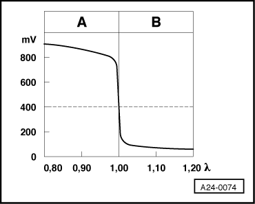
◆ The voltage signal for "Rich mixture (little residual oxygen)" is between about 0.6 and 1.0 V.
-
◆ The voltage signal for "Lean mixture (high level of residual oxygen)" is between about 0.0 and 0.3 V.
-
◆ During the transition from "rich" to "lean" and vice versa (λ = 1.0), there is a voltage jump from 0.6...1.0 V
to 0.0...0.3 V or vice versa.
Notes on display zones 3 and 4 continued:
-
◆ Because of the sharp voltage jump the lambda control cannot maintain a constant ideal mixture composition of λ = 1.0. The system fluctuates continuously between "slightly too lean" and "slightly too rich".
-
◆ The display value must intermittently drop below 0.3 V and exceed 0.6 V. Display values less than 0.45 V indicate "lean", whilst values over 0.45 V indicate "rich".
|