audi Workshop Repair Guides

Audi Workshop Service and Repair Manuals

TDI® diesel direct injection and glow plug system (4-cyl. unit injector) > < Testing knock sensor
Simos injection and ignition system (4-cylinder)
Testing ignition system
Checking Hall sender

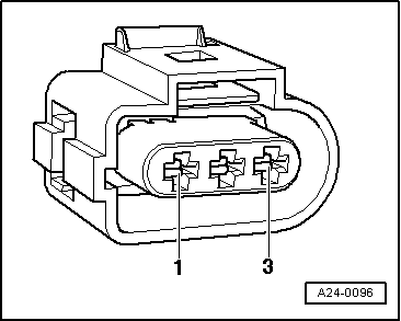
Fitting location of Hall sender .

Notes:

  • ◆ The Hall sender is located beneath the camshaft sprocket.
  • ◆ If no Hall sender signal is received, the knock sensor signals can no longer be assigned to the cylinders. If this happens, the knock control system is deactivated and the ignition timing is slightly retarded in order to prevent knocking.
  • ◆ Even if no Hall sender signal is received, the engine will continue to run and can also be re-started. The reason for this is as follows:
    • ‒ The fact that the control unit is out of phase by one crankshaft revolution does not have any noticeable effect on the injection system.
    • ‒ The fuel is injected upstream of the closed inlet valve instead of while the inlet valve is open. This has only a minor influence on the quality of the air/fuel mixture.
    • ‒ With the twin-spark ignition system an ignition spark is produced for each cylinder after every crankshaft revolution, and not after alternate revolutions as is normally the case.
  • ‒ Unplug connector from Hall sender.
  • ‒ Switch ignition on.

Note:

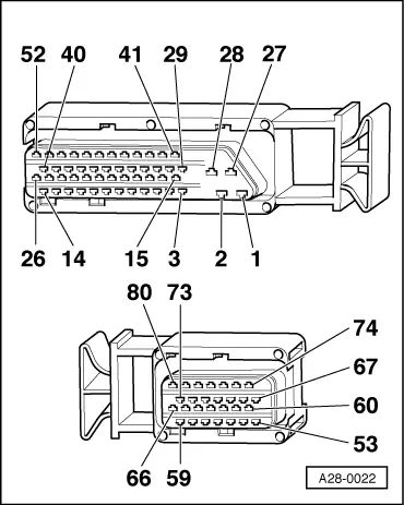
The connector contacts are numbered on the back of the connector.

 
A24-0096
  • ‒ → Connect hand-held multimeter V.A.G 1526 (voltage test range) between contact 1 (positive) and contact 3 (earth) on Hall sender connector. Make sure not to bend the contacts.

Specification: 4.5 ... 5.5 V

  • ‒ → Connect hand-held multimeter V.A.G 1526 (voltage test range) between contacts 2 and 3 (earth) on Hall sender connector. Make sure not to bend the contacts.

Specification: 4.5 ... 5.5 V

  • ‒ If the values are as specified, fit a new Hall sender.

Note:

The Hall sender receives its power supply from the engine control unit.

 
A24-0096
  • ‒ If the values are not as specified, test wiring between the Hall sender and engine control unit as follows:
  • ‒ Switch off ignition.
  • ‒ Connect test box V.A.G 1598/22 to the wiring harness for the engine control unit.
    => Page 24-13
  • ‒ → Test wiring from Hall sender...

 
A28-0022
  • ‒ → ...to engine control unit for open circuit and short to positive or earth.

Contact on 3-pin connector for Hall sender

Contact on control unit connector

1 (positive)

62

2 (signal)

76

3 (earth)

67

  • ‒ If the wiring is OK but the voltage readings are not as specified, fit a new engine control unit .

TDI® diesel direct injection and glow plug system (4-cyl. unit injector) > < Testing knock sensor