audi Workshop Repair Guides

Audi Workshop Service and Repair Manuals

Testing intake air temperature sender (vehicles without intake manifold change-over function) > < Designation of ignition coil terminals
Simos injection and ignition system (4-cylinder)
Testing ignition system
Testing twin-spark ignition system with two ignition coils

Fitting location .

Note:

The ignition coils and output stage are combined as a single component and cannot be renewed separately.

  • ‒ Unplug 4-pin connector from ignition coils.
 
A24-0094

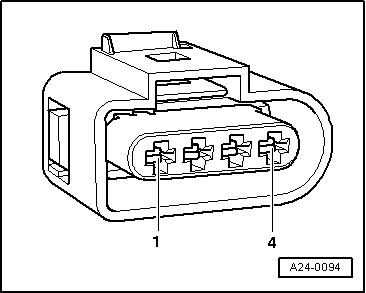
Testing earth connection to output stage

  • ‒ → Connect diode test lamp V.A.G 1527 between battery positive terminal and contact 4 (earth) of the connector. The diode test lamp should light up.
  • ‒ If the diode test lamp does not light up, test wiring between earth and contact 4 on 4-pin connector and rectify any open circuits.

=> Current flow diagrams, Electrical fault finding and Fitting locations binder

Testing power supply to ignition coils

Test requirement:

  • ‒ Fuse for ignition coils OK
  • ‒ Unplug 4-pin connector from ignition coils.
  • ‒ Switch ignition on.
 
A24-0094
  • ‒ → Connect diode test lamp V.A.G 1527 between engine earth and contact 2 (positive) of the connector.

Specification: the diode test lamp should light up.

  • ‒ If the result is not as specified, test wiring using current flow diagram. Rectify any faults and if necessary replace the fuse.

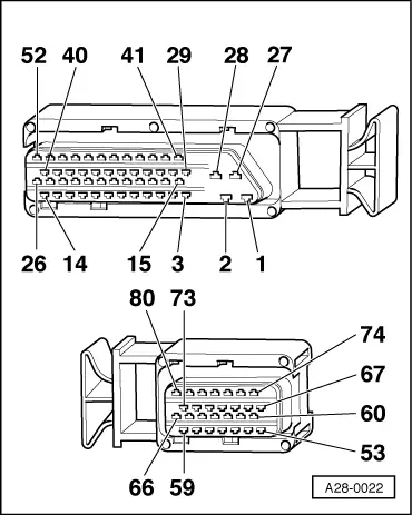
=> Current flow diagrams, Electrical fault finding and Fitting locations binder

Testing activation

  • ‒ Unplug the connectors from all four injectors (to prevent injection from occurring without ignition).
  • ‒ Connect diode test lamp V.A.G 1527 between engine earth and contact 1 of the 4-pin connector for the ignition coil.
  • ‒ On cars with manual gearbox, make sure that the gearstick is in neutral when carrying out the following step.
  • ‒ Have a second person operate the starter for a few seconds and check the diode test lamp. The diode test lamp should flash.
 
A28-0022
  • ‒ Connect diode test lamp V.A.G 1527 between engine earth and contact 3 of the 4-pin connector for the ignition coil.
  • ‒ Have a second person operate the starter for a few seconds and check the diode test lamp. The diode test lamp should flash.
  • ‒ → If the diode test lamp does not flash, test for open circuit or short to positive or earth in wiring between engine control unit and 4-pin connector for ignition coil using current flow diagram. (Connecting test box V.A.G 1598/22 to wiring harness for engine control unit .)
  • ‒ Rectify any open circuits or short circuits.

Contact on
4-pin connector for
output stage

Contact on
control unit connector

1
3

71
78

  • ‒ If no open circuits or short circuits are found, fit a new engine control unit
    => Page 24-15.
  • ‒ If the ignition wires, the power supply to the ignition coils and the output stage activation are OK but there is still no ignition spark, fit new ignition coils with output stage.
  • ‒ To do this, remove securing bolts for coolant tank and place tank to one side.
  • ‒ Remove throttle valve control part (seal off coolant hoses).
  • ‒ Renew ignition coils with output stage.

Notes:

  • ◆ Installation is carried out in the reverse sequence.
  • ◆ Renew seals and gaskets.
  • ◆ Tightening torque for securing bolts on ignition coil with output stage and on throttle valve control part: 9 Nm
  • ◆ After installation, perform adaption of throttle valve control part
    .

Testing intake air temperature sender (vehicles without intake manifold change-over function) > < Designation of ignition coil terminals