audi Workshop Repair Guides

Audi Workshop Service and Repair Manuals

Checking intake air system for leaks (unmetered air) > < Testing air mass meter (vehicles without intake manifold change-over function)
Simos injection and ignition system (4-cylinder)
Servicing Simos injection system
Testing air mass meter (vehicles with intake manifold change-over function)

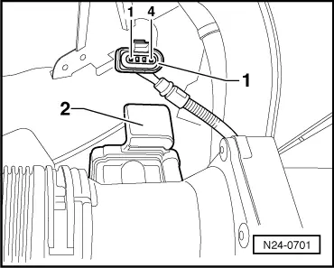
Note:

In vehicles with intake manifold change-over function, the intake air temperature sender is integrated in the air mass meter, and is therefore not fitted as a separate component on the engine.

Testing operation

Test conditions

  • ● Coolant temperature at least 80 °C
  • ● Electrical consumers switched off (radiator fan must not run during test)
  • ● Air conditioner switched off
  • ● On vehicles with automatic gearbox, the selector lever must be in position "P" or "N".
  • ● Fuse for air mass meter OK

=> Current flow diagrams, Electrical fault finding and Fitting locations binder

Test sequence

  • ‒ Connect fault reader V.A.G 1551 (V.A.G 1552) and select engine electronics control unit with the "Address word" 01. When doing this the engine must be running at idling speed.
    (Connecting fault reader and selecting engine electronics control unit=>Page 01-4.)
 
→ Indicated on display:
Rapid data transfer    HELP
Select function XX
  • ‒ Press keys 0 and 8 for the function "Read measured value block" and confirm entry with Q key.
 
→ Indicated on display:
Read measured value block    HELP
Input display group number XXX
  • ‒ Press keys 0, 0 and 1 for "Display group number 1" and confirm entry with Q key.
 
→ Indicated on display:
(1...4 = Display zones)
Read measured value block    1    ⇒
    1    2    3    4
  • ‒ Check whether the coolant temperature is above 80 °C in display zone 2.
  • ‒ Change to display group 2 as follows:
        V.A.G 1551: Press key 3
        V.A.G 1552: Press key ↑
 
→ Indicated on display:
(1...4 = Display zones)
Read measured value block 2    ⇒
    1    2    3    4

Display zone 2 shows the intake air mass (milligrams per stroke).

Specification: 100...280 mg/stroke

  • ‒ Press the ⇒key.
  • ‒ Press keys 0 and 6 for the "End output" function and confirm input with the Q key.
  • ‒ Switch off ignition.
  • ‒ If the values are not as specified or if the fault memory has recorded a fault relating to the air mass meter, test the power supply to the air mass meter=>Page 24-40.

Testing power supply to air mass meter

 
N24-0701
  • ‒ Test fuse for air mass meter.

=> Current flow diagrams, Electrical fault finding and Fitting locations binder

  • ‒ → If fuse is OK, disconnect 4-pin connector -1- from air mass meter -2-.
  • ‒ Connect multimeter to measure voltage on connector contacts 3 and engine earth.
  • ‒ Start engine and run at idling speed.

Specification: 11...15V.

 
N24-0701
  • ‒ Switch off ignition.
  • ‒ → If multimeter indicates zero voltage, test for open circuit and short to earth in wiring between fuse and contact 3 on connector. If necessary, repair wiring.

=> Current flow diagrams, Electrical fault finding and Fitting locations binder

  • ‒ If the fuse and the wiring are OK but the meter still indicates zero voltage, test the fuel pump relay=>Page 24-33.
 
N24-0567
  • ‒ If the power supply is OK, test the signal wire.

Testing signal wiring for air mass meter

  • ‒ → Connect test box V.A.G 1598/22 to control unit wiring harness.
 
N24-0701
  • ‒ → Test wiring from plug connector on air mass meter...

 
N24-0567
  • ‒ → ... to engine control unit for open circuit and short to positive or earth. Rectify if necessary.

Plug connector for air mass meter G70

Test box V.A.G 1598/22 or control unit connector

1

13

2

12

  • ‒ If the wiring is OK, fit a new air mass meter -G70.

Checking intake air system for leaks (unmetered air) > < Testing air mass meter (vehicles without intake manifold change-over function)