audi Workshop Repair Guides

Audi Workshop Service and Repair Manuals

Servicing unit injector > < Servicing intake manifold flap
TDI® diesel direct injection and glow plug system (4-cyl. unit injector)
Servicing diesel direct injection system
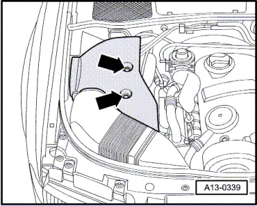
Testing intake manifold flap change-over function
 
G24-0039

Special tools and workshop equipment required

  • ◆ V.A.G 1390
  • ◆ V.A.G 1526 A
  • ◆ V.A.G 1527 B
  • ◆ V.A.G 1594 A
  • ◆ V.A.G 1598/31

Checking function

  • ‒ Start engine and run at idling speed.
  • ‒ Switch off ignition.
  • ‒ Observe positioning lever on intake manifold flap (2nd person required).
    • ‒ After switching off the ignition, the intake manifold flap should close and open again after approx. 3 seconds.

If change-over does not occur, the following checks must be carried out.

  • ‒ Check intake manifold flap change-over mechanics for freedom of movement. To do this operate rods by hand.
  • ‒ Check function of vacuum positioning element with hand vacuum pump V.A.G 1390.
  • ‒ Check vacuum pipes for correct connection.
 
A13-0339

If no fault is found in the mechanical components:

  • ‒ Unclip protecting covers.
  • ‒ → Unscrew bolts -arrows- and remove air cleaner cover.
  • ‒ Unplug connector on intake manifold flap change-over valve -N239.

 
N23-0016

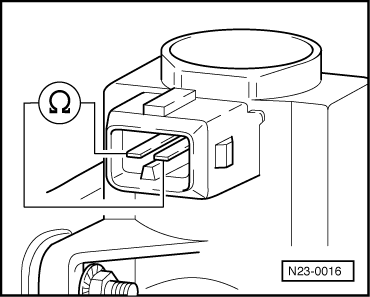
Testing internal resistance

  • ‒ → Connect multimeter to valve (resistance measurement range)
    • ‒ Specification: 25 ... 45 ω

If the specification is not obtained:

  • ‒ Renew intake manifold flap change-over valve.
 
V96-0749

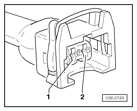
Checking voltage supply

Test requirement:

  • ● Fuse for intake manifold flap change-over valve OK
  • ‒ → Connect multimeter (voltage measurement range) as follows:

Connector
Contact

Measure against

1

Engine earth

  • ‒ Switch on ignition.
    • ‒ Specification: approx. battery voltage

If the specification is not obtained:

  • ‒ Test wiring for open circuits and rectify if necessary.
 
V96-0749

Checking activation

  • ‒ → Connect voltage tester V.A.G 1527 B between contacts 1 and 2
  • ‒ Start final control diagnosis and select intake manifold flap change-over valve -N239 =>Page 01-55.
    • ‒ The LED should flash slowly.

Note:

The LEDs on voltage testers with a low current draw continue to glow faintly between impulses from the engine control unit (rather than going out completely) and become much brighter when receiving an impulse.

  • ‒ Finish off final control diagnosis.
  • ‒ Select diagnosis function "06 - End output" Page 01-11.
  • ‒ Switch off ignition.

If the LED does not react as described:

  • ‒ Connect test box V.A.G 1598/31 to wiring harness for engine control unit. Do not connect to the engine control unit itself.
    => Page 23-37.
 
V96-0749
  • ‒ → Test for open circuit and short to positive or earth in the following wiring connections:

Connector
Contact

Test box V.A.G 1598/31
Socket

2

81

  • ‒ Rectify any open/short circuit as necessary.

If no fault is found:

  • ‒ Fit a new engine control unit => Page 23-40.

Servicing unit injector > < Servicing intake manifold flap