audi Workshop Repair Guides

Audi Workshop Service and Repair Manuals

Testing control unit input values > < Renewing engine control unit
TDI® diesel direct injection and glow plug system (4-cyl. unit injector)
Servicing diesel direct injection system
Testing voltage supply for diesel direct injection system
 
G24-0020

Special tools and workshop equipment required

  • ◆ V.A.G 1526 A
  • ◆ V.A.G 1594 A
  • ◆ V.A.G 1598/31

With the ignition switched on, the injection system receives its voltage supply via terminal 30 voltage supply relay -J317.

In order for relay -J317 to close, a voltage must be applied to the Diesel direct injection system control unit via terminal 15. This means that relay -J317 is only earthed (via the Diesel direct injection system control unit) if a voltage is applied to the control unit via terminal 15.

 
A97-0131

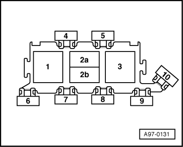
Note:

→ Fitting location of terminal 30 voltage supply relay -J317:plug-in position 3 on relay and fuse carrier in electronics box in plenum chamber.

Test requirement:

  • ● Battery voltage not less than 12.7 V

Test sequence

  • ‒ Connect test box V.A.G 1598/31 to wiring harness for engine control unit. Do not connect to the engine control unit itself.
    => Page 23-37.

Testing earth supply

  • ‒ Connect multimeter (voltage measurement range) as follows:

Test box V.A.G 1598/31
Socket

Measure against

4

Battery positive

5

Battery positive

    • ‒ Specification: approx. battery voltage

If the specifications are not obtained:

  • ‒ Check wiring connections according to current flow diagram.

Checking voltage supply (terminal 15)

  • ‒ Connect multimeter (voltage measurement range) as follows:

Test box V.A.G 1598/31
Socket

Measure against

37

Engine earth

  • ‒ Switch on ignition.
    • ‒ Specification: approx. battery voltage

If the specification is not attained:

  • ‒ Test wiring for open circuits and rectify if necessary.
 
A23-0068

Testing voltage supply (terminal 30)

  • ‒ → Connect sockets 4 and 18 of test box to each other using auxiliary cable from V.A.G 1594 A.

 
A97-0131
    • ‒ → The relay -J317 (plug-in position 3 on relay and fuse carrier in electronics box in plenum chamber) should pick up audibly and perceptibly

If the relay does not pick up:

  • ‒ Check relay -J322 => Page 23-50.

If the relay picks up

  • ‒ Connect multimeter (voltage measurement range) as follows:

Test box V.A.G 1598/31
Socket

Specification

1 + 5

approx. battery voltage

2 + 5

approx. battery voltage

 
A97-0131
  • ‒ → Test the following wiring connections for open circuits:

Plug-in position 3 on relay and fuse carrier in electronics box in plenum chamber
Contact

Test box V.A.G 1598/31
Socket

8

1

8

2

If no fault is detected in the wiring:

  • ‒ Test relay -J322.

Testing terminal 30 voltage supply relay -J317

Requirements for test:

  • ● Earth connection and voltage connection of engine control unit okay
  • ● Engine control unit connected.
  • ● Relay clicks when ignition is switched on.
  • ‒ Unplug relay -J317 from relay panel (plug-in position 3 on relay and fuse carrier in electronics box in plenum chamber).
 
A97-0131
  • ‒ → Connect multimeter (voltage measurement range) as follows:

Plug-in position 3 on relay and fuse carrier in electronics box in plenum chamber
Contact

Measure against

1

Engine earth

2

Engine earth

    • ‒ Specification: approx. battery voltage

If the specification is not attained:

  • ‒ Test for open circuits in wiring, rectify if necessary.
  • ‒ Connect multimeter (voltage measurement range) as follows:

Plug-in position 3 on relay and fuse carrier in electronics box in plenum chamber
Contact

Measure against

4

Battery positive

  • ‒ Switch on ignition.
    • ‒ Specification: approx. battery voltage

If the specification is not attained:

 
A97-0131
  • ‒ → Test for open circuit and short to positive or earth in the following wiring connections:

Plug-in position 3 on relay and fuse carrier in electronics box in plenum chamber
Contact

Test box V.A.G 1598/31
Socket

4

18

If no wiring fault is detected:

  • ‒ Fit a new engine control unit => Page 23-40.

If no wiring fault is detected and no voltage was present between contacts 1+2:

  • ‒ Renew relay -J317.

Testing control unit input values > < Renewing engine control unit