audi Workshop Repair Guides

Audi Workshop Service and Repair Manuals

Dynamically checking and adjusting commencement of injection: engine code AFF, AHU, AFN, AVG > < Servicing injection pump: engine code AHH
TDI diesel injection and glow plug system (4-cyl.) 08.99 ä
Servicing Diesel direct injection system
Removing and installing injection pump: engine codeAFF, AHU, AFN,AVG

Removing injection pump

 
V28-0833
  • ‒ Move lock carrier to service position

=> General body repairs, Exterior; Repair group 50; Body, front; Lock carrier - service position

  • ‒ Remove upper toothed belt guard and cylinder head cover.
  • ‒ Turn crankshaft to TDC No. 1 cylinder.
  • → TDC on vehicles with manual gearbox

 
N13-0361
  • → TDC on vehicles with automatic gearbox

Engine removed - vehicles with manual gearbox:

 
V13-0899
  • ‒ → Install adjustment device 2068 A as shown.
  • ‒ Set adjustment device to 107 mm -arrow -. The left-hand mark on the scale is the reference point.
  • ‒ Turn crankshaft until TDC marking on flywheel aligns with point of setting device.

Engine removed - vehicles with automatic gearbox:

 
A13-0211
  • ‒ → Install adjustment device 2068 A as shown.
  • ‒ Set adjustment device to 99 mm -arrow-. The left-hand mark on the scale is the reference point.
  • ‒ Turn crankshaft until TDC marking on flywheel aligns with point of setting device.
 
V13-1151
  • ‒ → Lock camshaft with setting bar.
  • ‒ Centralize setting bar as follows:
    Turn arrested camshaft so that one end of setting bar contacts the cylinder head. Using feeler gauge establish the gap at the other end of the setting bar. Place a feeler gauge corresponding to half the gap between setting bar and cylinder head. Turn camshaft until the setting bar contacts the feeler gauge. Place a 2nd feeler gauge, of same thickness, at the other end between setting bar and cylinder head.
  • ‒ Remove idler roller.
  • ‒ Remove tensioning roller nut.
 
V23-0077
  • ‒ Relieve tooth belt tension and take off camshaft and injection pump sprockets.
  • ‒ Lock injection pump sprocket with pin 2064.
  • ‒ Remove injection pump sprocket securing nut.
  • ‒ → Loosen puller arms and offer up.
  • ‒ Locate puller arms through holes in injection pump sprocket and tighten.
  • ‒ Place injection pump sprocket under tension with puller.
 
V23-0077
  • ‒ → Release injection pump sprocket from injection pump taper by tapping lightly on puller spindle -arrow- (when doing this hold sprocket so that it does not fall off).
  • ‒ Unbolt all fuel lines at fuel pump.
  • ‒ Cover openings with a clean cloth.

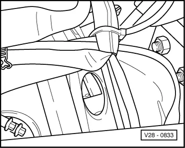
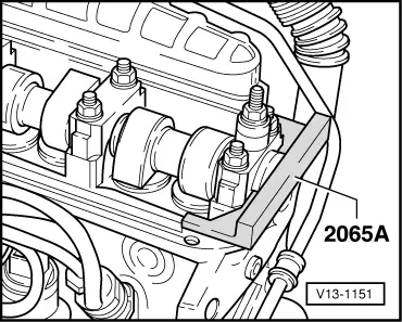
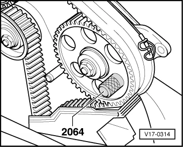
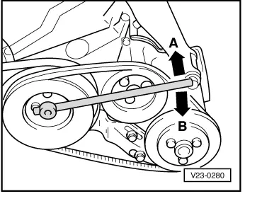
Note:

Use slotted ring spanner 3035 to remove high pressure fuel pipes.

 
V23-0300
  • ‒ Unplug connector for fuel cut-off valve/commencement of injection valve.
  • ‒ Disconnect quantity adjuster connector and unclip connector from retainer.
  • ‒ → Remove securing bolts from console -arrows-.
 
V23-0301
  • ‒ → Then remove bolt from rear support -arrow-.
  • ‒ Take off injection pump.

Installing injection pump

  • ‒ Insert injection pump into console and then tighten securing bolt on rear support with conical nut first.
  • ‒ Align injection pump to central position in console elongated holes and secure hand tight.
 
V17-0314
  • ‒ → Install injection pump sprocket and lock in position with pin 2064. When installing observe spring washer seating.
  • ‒ Tighten securing nut to 45 Nm.
  • ‒ Loosen camshaft sprocket securing bolt a half turn.
 
V13-0897
  • ‒ → Place a drift through hole in the rear of the toothed belt guard and release the camshaft sprocket from camshaft taper with a blow from a hammer.
  • ‒ Take camshaft sprocket off.
  • ‒ Check whether TDC mark on flywheel and reference mark are aligned.
  • ‒ Place tooth belt on injection pump sprocket and tensioning roller.
  • ‒ Fit camshaft sprocket into toothed belt and secure sprocket so that the camshaft can still turn.
 
N13-0027
  • ‒ Install idler roller.
  • ‒ Remove locking pin from injection pump sprocket.
  • ‒ → Tension toothed belt. Using pin wrench (e.g. Matra V159) on eccentric turn clockwise until the notch and the raised mark -arrows- align.
  • ‒ Tighten securing nut to 20 Nm.
  • ‒ Check TDC mark on flywheel again.
  • ‒ Tighten camshaft sprocket securing bolt to
    45 Nm.
  • ‒ Remove setting bar 2065A from camshaft.
  • ‒ Turn crankshaft two rotations in engine D.O.R. until crankshaft is set to TDC No. 1 cylinder again.

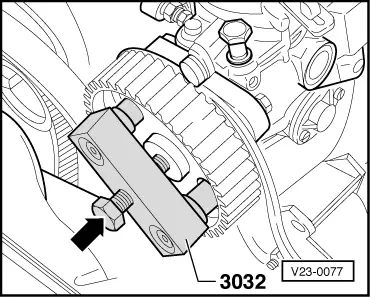
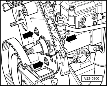
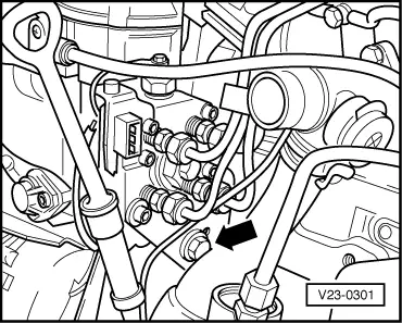
Adjusting injection pump

 
V23-0321

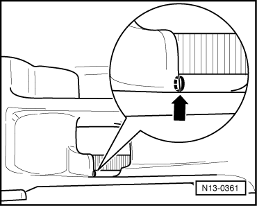
Checking and adjustment conditions

  • ● Mechanical engine basic setting OK.
  • ● Toothed belt tension OK.
  • ● Engine at TDC.
  • ‒ → Remove screw plug on injection pump and screw in adapter 3313 for dial gauge.
  • ‒ Insert dial gauge with needle plunger into adapter.
  • ‒ Pre-load dial gauge to about 2 mm and tighten adjusting nut on adapter.
 
V23-0280
  • ‒ → Rotate crankshaft slowly in direction -A- (against direction of engine revolution) until needle on dial gauge stops moving.
  • ‒ Slacken dial gauge, then re-tighten with a pre-load of about 1 mm.
  • ‒ Set measuring scale to 0.
  • ‒ → Rotate crankshaft slowly in direction -B- (direction of engine revolution) until marking -0- on flywheel aligns with reference mark or edge of setting bar.

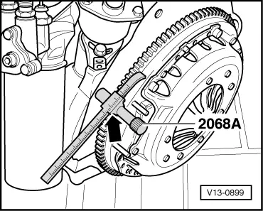
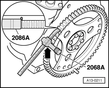
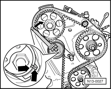
Note:

Alignment with the TDC mark is achieved by rotating the crankshaft in the direction of engine revolution. If the crankshaft is rotated too far by mistake (i.e. beyond the TDC mark), adjust as follows:

 
V23-0321
  • ‒ Rotate crankshaft in opposite direction until dial gauge reads 0 again, then rotate again until TDC mark is reached.
  • ‒ → Read off commencement of delivery on dial gauge.
  • Specification: 0.7 ±0.02 mm stroke
  • ‒ Adjust commencement of delivery by turning injection pump.

Tightening torques:

  • Securing bolts for injection pump: 25 Nm
  • Screw plug: 20 Nm
  • ‒ Reconnect injection pipes, fuel supply pipe and electrical wiring.
 
A20-0338

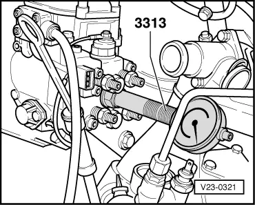
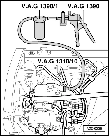
→ Fill injection pump with clean diesel fuel as follows:

    • ‒ Screw adapter V.A.G 1318/10 into return pipe connection on injection pump.
    • ‒ Connect vacuum hand pump V.A.G 1390 to return pipe connection together with bleeder container V.A.G 1390.
    • ‒ Operate vacuum hand pump until bubble-free fuel comes out of return pipe connection. Do not allow the fuel to enter the vacuum pump.
  • Reconnect return pipe to injection pump (with tightening torque of 25 Nm).
  • Install toothed belt guard and cylinder head cover.
  • Dynamically check and adjust commencement of injection
    =>Page 23-26.

Dynamically checking and adjusting commencement of injection: engine code AFF, AHU, AFN, AVG > < Servicing injection pump: engine code AHH