audi Workshop Repair Guides

Audi Workshop Service and Repair Manuals

Checking fuel temperature sender -G81 > < Checking injection timing control range
TDI diesel injection and glow plug system (4-cyl.) 08.99 ä
Testing injection control
Checking commencement of injection valve
 
A23-0036

Electrical test of commencement of injection valve

  • ‒ Unplug connector for commencement of injection valve
    =>Fitting locations overview, Page 23-4.

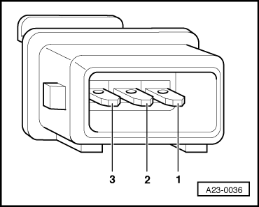
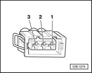
Measuring resistance on vehicles with 3-pin connector:

  • ‒ → Connect hand-held multimeter (resistance test range) between contacts 2 and 3.
  • Specification: 12...20ω
 
A23-0028

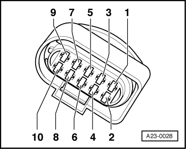
Measuring resistance on vehicles with 10-pin connector:

  • ‒ → Connect hand-held multimeter (resistance test range) between contacts 9 and 10.
  • Specification: 12...20 ω

If the specification is not obtained:

  • ‒ Renew commencement of injection valve (N108).
 
V28-1074

If the specification is obtained:

Testing voltage supply of commencement of injection valve

Measuring voltage on vehicles with 3-pin connector:

  • ‒ → Connect hand-held multimeter (voltage test range) between engine earth and contact 3 on the connector.
  • ‒ Switch ignition on.
 
A23-0028
  • Specification: approx. battery voltage

Measuring voltage on vehicles with 10-pin connector:

  • ‒ → Connect hand-held multimeter (voltage test range) between engine earth and contact 10 on the connector.
  • ‒ Switch ignition on.
  • Specification: approx. battery voltage

If the specification is not obtained:

  • ‒ Connect test box V.A.G 1598/31 to wiring harness for engine control unit. Do not connect to the engine control unit itself.
    .
 
V28-1074

The following wiring connections are to be checked for open circuits and/or short to positive or negative.

→ Testing wiring connection on vehicles with 3-pin connector.

3-pin connector on wiring harness, contact

Test box V.A.G 1598/31, socket

2

114

3

1 and 2

 
A23-0028

→ Testing wiring connections on vehicles with 10-pin connector.

10-pin connector on wiring harness, contact

Test box V.A.G 1598/31, socket

9

114

10

1 and 2

  • ‒ Rectify any open/short circuit as necessary.

=> Current flow diagrams, Electrical fault finding and Fitting locations binder

Checking fuel temperature sender -G81 > < Checking injection timing control range