-
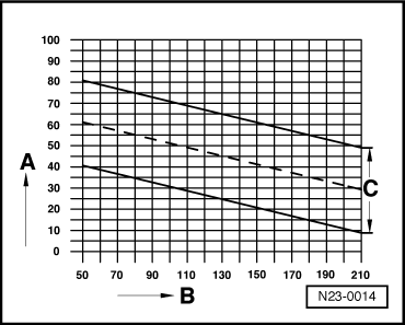
‒ → The commencement of injection value in display zone 2 varies in accordance with the fuel temperature value in display zone 9.
- Specification: => range C in illustration
- A - Zone 2 commencement of injection
- B - Zone 9 fuel temperature
Notes:
-
◆ If the commencement of injection is advanced turn injection pump in engine direction of rotation, if the commencement of injection is retarded turn against direction of rotation.
-
◆ If when checking the commencement of injection the specifications are within zone -C- then no adjustment is required. After repairs e.g. removing and installing injection pump, adjusting timing then the commencement of injection is to be set to the mean valve (dashed line) of specification zone -C-.
If the specifications within zone C are not met:
-
‒ Adjust commencement of injection => Page 23-26.
Display Group 03 at idling speed
This display group is used for testing the exhaust gas recirculation. The exhaust gas recirculation valve -N18 opens and closes alternately for periods of 10 seconds.
|
|
|
|
|
|
System in basic setting 3
|
⇒
|
◂ Indicated on display
|
|
|
|
860 rpm
|
EGR active
|
200 mg/H
|
99 %
|
|
|
|
|
|
|
|
|
Duty cycle (activation) of exhaust gas recirculation valve
|
|
|
|
|
|
|
Intake air mass
|
|
|
|
|
|
Exhaust gas recirculation valve -N18 open
|
|
|
|
|
Engine speed
|
|
|
|
|
|
|
|
|
|
|
|
System in basic setting 3
|
⇒
|
◂ Indicated on display
|
|
|
|
860 rpm
|
EGRn.active
|
420 mg/H
|
0 %
|
|
|
|
|
|
|
|
|
Duty cycle (activation) of exhaust gas recirculation valve
|
|
|
|
|
|
|
Intake air mass
|
|
|
|
|
|
Exhaust gas recirculation valve -N18 closed
|
|
|
|
|
Engine speed
|
|
|
|
|
|
Display Group 11 at idling speed
This display group is used for testing the boost (charge) pressure control. The boost pressure control solenoid valve -N75 opens and closes alternately for periods of 10 seconds.
|
|
|
|
|
|
System in basic setting 11
|
⇒
|
◂ Indicated on display
|
|
|
|
860 rpm
|
On
|
969 mbar
|
0 %
|
|
|
|
|
|
|
|
|
Activation of boost pressure control solenoid valve
|
|
|
|
|
|
|
Boost pressure
|
|
|
|
|
|
Boost pressure control solenoid valve open
|
|
|
|
|
Engine speed
|
|
|
|
|
|
|
|
|
|
|
|
System in basic setting 11
|
⇒
|
◂ Indicated on display
|
|
|
|
860 rpm
|
Off
|
948 mbar
|
99 %
|
|
|
|
|
|
|
|
|
Activation of boost pressure control solenoid valve
|
|
|
|
|
|
|
Boost pressure
|
|
|
|
|
|
Boost pressure control solenoid valve closed
|
|
|
|
|
Engine speed
|
|
|
|
|
|
|