audi Workshop Repair Guides

Audi Workshop Service and Repair Manuals

Testing signals from and to automatic gearbox > < Checking -G149 sensor for modulating piston movement and -N146 metering control
TDI Injection and Glow Plug System (4-cyl.) 07.97 > 07.99
Testing control unit input values
Checking air mass meter -G70

The signal from the air mass meter is required by the control unit to calculate the required injection quantity and to control the exhaust gas recirculation. The weaker the signal from the air mass meter, the less fuel can be injected.

  • ‒ Connect fault reader V.A.G 1551 (V.A.G 1552) and select the engine electronics control unit using "Address word" 01. For this purpose, the engine must be running at idling speed.
    (Connecting fault reader and selecting engine electronics control unit .)
 
→ Indicated on display:
Rapid data transfer     HELP
Select function XX
  • ‒ Press keys 0 and 8 for the function "Read measured value block" and confirm entry with Q key.
 
→ Indicated on display:
Read measured value block HELP
Enter display group number XXX
  • ‒ Press keys 0.1 and 0 for "display group number 10" and confirm entry by pressing Q key.
 
→ Indicated on display:
Read measured value block 10        ⇒
    309 mg/stroke     1030 mbar     1011 mbar 0.0 %
  • ‒ Observe readout in display zone 1.
 
→ Specified value: 230 ... 370 mg/stroke
Read measured value block 10        ⇒
    309 mg/stroke     1030 mbar     1011 mbar    0.0 %

If specified value is not attained:

  • ‒ Check exhaust gas recirculation:

=> 4-cyl. Diesel direct - injection system (TDI), Mechanical Components; Repair group 26; Checking exhaust gas recirculation system

If specified value is attained:

  • ‒ Perform a road test.
Important:
Secure fault reader to the rear seat and operate from this location. When doing this, always observe the relevant safety precautions Page 23-1.
  • ‒ Accelerate the vehicle from approx. 1500 rpm at full throttle, manual gearbox should be in 2nd gear, automatic gearbox should be in position 2.
  • ‒ At approx. 3000 rpm, press the PRINT key on the V.A.G 1551. The accelerator pedal must be fully depressed at this point.
 
→ Specification for display zone 4: 100 % (accelerator pedal position)
Read measured value block 10        ⇒
    830 mg/stroke     1030 mbar     1850 mbar    100 %

If specified value is not attained:

  • ‒ Repeat test and accelerate vehicle at full throttle.
 
→ Specification for display zone 3: Boost pressure
Read measured value block 10        ⇒
    830 mg/stroke    1030 mbar    1850 mbar    100 %
  • Engine codes: AFF, AHU, AHH 1800 ... 2050 mbar
  • Engine code: AFN 1800 ... 2250 mbar
  • If specified value is not attained:

    • ‒ Test boost pressure

    => 4-cyl. Diesel direct injection system (TDI), Mechanical Components; Repair group 21; checking boost pressure system

     
    → Specification for display zone 1: > 800 mg/stroke (intake air mass)
    Read measured value block 10        ⇒
        830 mg/stroke    1030 mbar    1850 mbar    100 %
  • Engine codes: AFF, AHU, AHH
    greater than 750 mg/stroke
  • Engine code: AFN
    greater than 800 mg/stroke
  • If specified value is not attained:

    • ‒ Replace air mass meter (G70).

    If display zone 1 shows a constant reading of 425 mg/stroke (fixed substitute value):

    • Substitute value for 66 kW vehicles 425 mg/stroke
    • Substitute value for 81 kW vehicles 550 mg/stroke
     
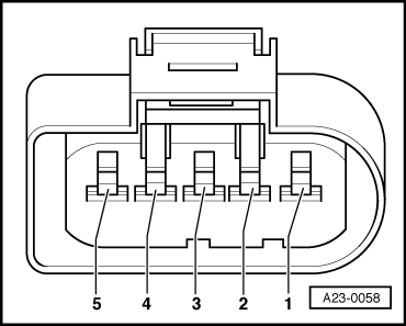
    A23-0058
    • ‒ Switch ignition off.
    • ‒ Remove connector from air mass meter => Fitting location overview, Page 23-4
    • ‒ Switch the ignition on.
    • ‒ → Connect hand-held multimeter (voltage range) between the following contacts on the connector:

    5-pin connector on the wiring harness, contact.

    Specified value

    2 + earth

    Battery voltage

    2 + 3

    Battery voltage

    4 + earth

    approx. 5 V

    4 + 3

    approx. 5 V

    If the specified values are not obtained:

    • ‒ Connect test box V.A.G 1598/22 to wiring harness for engine control unit .
     
    A23-0058

    The following wiring connections are to be checked for open circuits and/or short to positive or negative.

    5-pin connector on the wiring harness, contact

    Test box V.A.G 1598/22, socket

    1

    -

    2

    2, 28

    3

    1, 27

    4

    50

    5

    52

    • ‒ Rectify any open/short circuit as necessary.

    => Current Flow Diagrams, Electrical Fault-finding and Fitting Locations binder

    Testing signals from and to automatic gearbox > < Checking -G149 sensor for modulating piston movement and -N146 metering control