
A4 Mk1
|
Testing injection control
Checking valve for commencement of injection
|
 |
|
|
Check valve for commencement of injection electrically
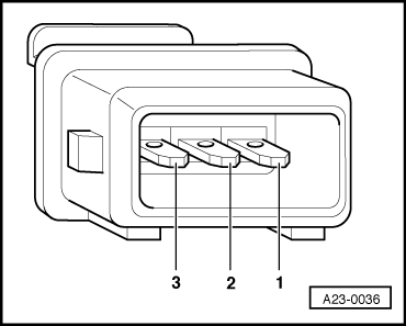
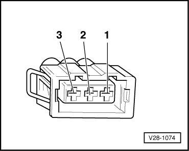
Resistance measurement on vehicles with 3-pin connector.
|
 |
|
|
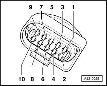
Resistance measurement on vehicles with 10-pin connector.
If specified value is not attained:
|
 |
|
|
If specified value is attained: Check power supply for valve for commencement of injection Resistance measurement on vehicles with 3-pin connector.
|
|
|
Voltage measurement on vehicles with 10-pin connector.
If specified value is not attained:
|
|
|||||||
|
The following wiring connections are to be checked for open circuits and/or short to positive or negative. → Wiring measurement on vehicles with 3-pin connector.
|
|
|||||||
|
→ Wiring measurement on vehicles with 10-pin connector.
=> Current Flow Diagrams, Electrical Fault-finding and Fitting Locations binder |