audi Workshop Repair Guides

Audi Workshop Service and Repair Manuals

Bleeding fuel system > < Overview of fitting locations
Removing and installing injection pump
Removing injection pump
–  Obtain radio anti-theft code, then switch off ignition and disconnect battery earth strap.
–  Move lock carrier to service position → Rep. Gr.50.
–  Remove viscous fan.
–  Remove toothed belt covers (front left and right).
   
–  Remove front section of intake manifold.
–  Open oil filler cap.
  A23-0046
–  Turn engine until the marking “- OT -” (TDC) is visible on camshaft.
  Note
Turn over the engine at the central bolt on the crankshaft.
–  Unscrew plug for TDC marking from crankcase. The crankshaft is provided with a TDC drilling, which can be felt directly below the plug.
  A23-0056
–  Screw locking pin -3242- into threaded hole where plug has been removed, and tighten.
  V13-0831
–  Remove vibration damper on injection pump sprocket (bolts -1-).
  Note
Do NOT loosen nut -2- for injection pump sprocket. Otherwise this would alter the basic setting of the injection pump. The setting cannot be re-adjusted with workshop equipment.
–  Mark direction of rotation of toothed belt. The belt can break if it rotates in the opposite direction when refitted.
  A23-0047
–  Slacken toothed belt tensioner and take off toothed belt.
–  Unplug connector from injection pump.
–  Disconnect fuel supply and return pipes from injection pump.
–  Cover open connections with a clean cloth.
–  Disconnect injector pipes from injectors using open ring spanner -3035-.
  A23-0049
–  Unscrew injection pump mountings.
–  Lift out injection pump together with injector pipes.
–  Disconnect injection pipes.
Installing injection pump
  A23-0050
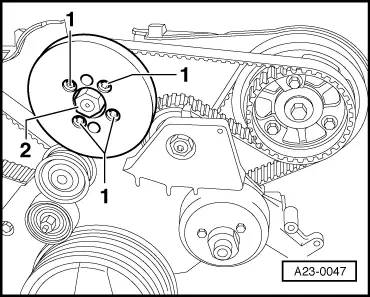
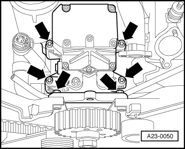
–  Mount injection pump on engine and bolt it in place.
t  Tightening torque: bolts on crankcase: 20 Nm
t  Tightening torque: bolts on toothed belt cover: 10 Nm
–  After tightening injection pump mountings, fit injector pipes one at a time, working from bottom to top and secure using torque wrench -V.A.G 1331- and 17 mm open ring spanner attachment (e.g. Stahlwille 733/10).
t  Tightening torque: 30 Nm
  Note
t  Incorrect assembly will distort the taper seats of the pipe unions. (Risk of leaks)
t  When tightening the connections, make sure the injector pipes are not twisted or under tension.
t  Secure the retaining clips on the injector pipes in their original positions and without tension.
–  Secure injector pipes to injectors.
t  Tightening torque: 30 Nm
  A23-0050
–  Lock injection pump sprocket with diesel injection pump locking pin -3359-.
  A23-0052
–  Slacken camshaft sprocket -1- and align centrally in longitudinal holes.
–  Fit toothed belt. Pay attention to the direction of rotation as marked upon removal.
  A23-0053
–  Tension toothed belt. To do this, turn Allen key anti-clockwise until the markings align, and then tighten the securing nut.
t  Tightening torque: 36 Nm
–  Tighten bolts at camshaft sprocket.
t  Tightening torque: 20 Nm
  A23-0048
–  Remove diesel injection pump locking pin -3359-.
  A23-0052
–  Remove locking pin -3242-.
–  Turn crankshaft two rotations in normal direction of rotation until it is set to TDC of No. 3 cylinder again.
–  Recheck markings at toothed belt tensioner. Correct toothed belt tension as necessary.
  V13-0831
–  Install vibration damper on injection pump sprocket (bolts -1-).
t  Tightening torque: 20 Nm
  A23-0047
–  Install front section of intake manifold.
t  Tightening torque: 10 Nm
–  Fit connector to injection pump.
–  Connect fuel pipes.
–  Install viscous fan.
–  Install lock carrier → Rep. Gr.50.
After installing the injection pump, the following steps must be performed:
l  Bleed fuel system, otherwise engine will not start → Chapter.
l  Dynamically check and adjust commencement of injection → Chapter.
  A23-0046

Bleeding fuel system > < Overview of fitting locations