
A4 Mk1
|
Steering box (left-hand drive)
Removing and installing power-assisted steering box (RS4)
Special tools and workshop equipment required
Removing
=> Electrical System; Repair Group 27; Battery; Removing and installing battery
Attention:
Move steering wheel to centre position and do not turn it whilst performing repair work, as otherwise coil connector of airbag unit could be damaged.
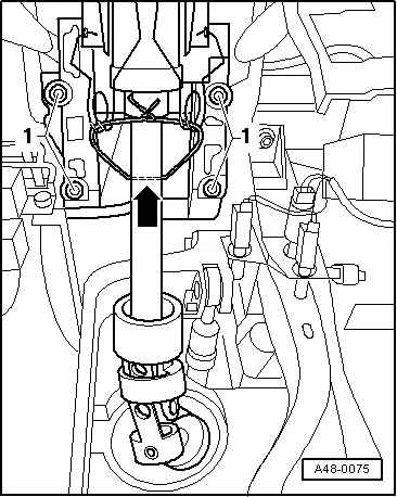
Uncontrolled turning of steering wheel with steering box removed could strain and damage coil connector of airbag system. An assembly lock is required to prevent top and bottom parts of steering column being pulled apart when pulling off steering box. Mesh section will become separated if top and bottom parts of steering column are pulled too far apart or excessively telescoped. Rattling noise may subsequently be encountered if mesh section is no longer in its original installation position. |
 |
|
|
 |
|
|
 |
|
|
 |
|
|
 |
|
|
 |
|
|
 |
|
|
 |
|
|
 |
|
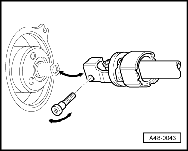
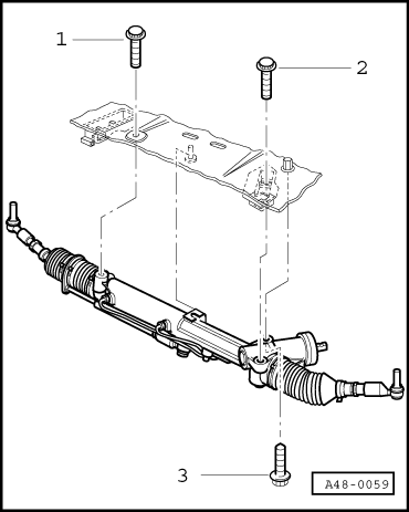
Left gearbox support must be removed before bolt -3- can be screwed out.
=> Manual Gearbox; Repair Group 34; Removing and installing gearbox => Automatic Gearbox; Repair Group 37; Removing and installing gearbox |
 |
|
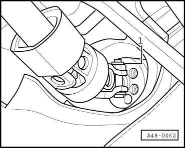
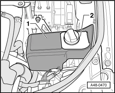
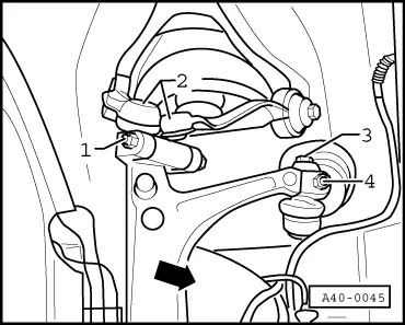
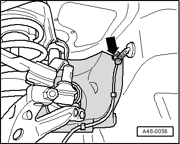
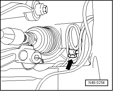
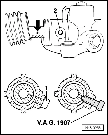
Note: Bolt -arrow- is only accessible through recess in shield between Lambda probe -1- and front exhaust pipe -2-.
|
 |
|
|
 |
|
|
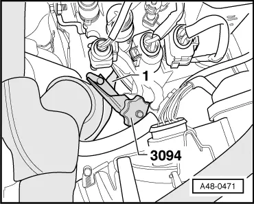
The following operations require two mechanics
|
 |
|
|
 |
|
|
Installing → Centre steering box removed with -V.A.G 1907-.
|
|
|
Make sure threads and contact surfaces of bolts are free from oil/grease.
|
|
|
Note: Bolt -arrow- is only accessible through recess in shield between Lambda probe -1- and front exhaust pipe -2-.
|
|
|
|
|
|
=> Manual Gearbox; Repair Group 34; Removing and installing gearbox => Automatic Gearbox; Repair Group 37; Removing and installing gearbox Notes:
Notes:
|
|
|
Tighten torques:wheel bearing housing:
|
|
|
=> Electrical System; Repair Group 27; Battery; Removing and installing battery |