|
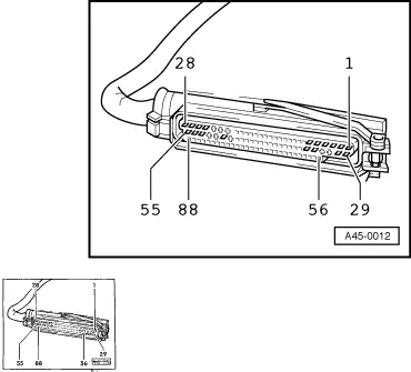
→ Socket designations of test box V.A.G 1598/20 are identical with contact designations on control unit -J104 as well as those on wiring harness connector.
=> Current Flow Diagrams, Electrical Fault-finding and Fitting Locations binder
-
‒ Connect test box V.A.G 1598/20 to multi-pin connector on ABS harness.
Contact assignment of wiring harness/control unit -J104 multiple connector.
|
|
|---|
|
Contact
|
Wiring to component...
|
|
1
|
Voltage supply from terminal 15
|
|
2
|
Hydraulic unit; actuation of return pump relay -J105
|
|
3
|
Hydraulic unit; change-over valve (secondary piston circuit) -N168
|
|
4
|
Hydraulic unit; EDL outlet valve -N169
|
|
5
|
Hydraulic unit; inlet valve, front left -N101
|
|
6
|
Hydraulic unit, inlet valve rear right -N133
|
|
7
|
Hydraulic unit; actuation of return pump relay -J105
|
|
9
|
Front left speed sensor -G47
- Vehicles with FWD and ABS/EDL
- Vehicles with FWD and ABS/EDL/TCS
|
|
10
|
Front left speed sensor -G47
|
|
11
|
Rear right speed sensor -G44
|
|
12
|
Rear left speed sensor -G46
|
|
13
|
Rear left speed sensor -G46
|
|
14
|
Front right speed sensor -G45
|
|
15
|
Front right speed sensor -G45
- Vehicles with FWD and ABS
- Vehicles with FWD and ABS/EDL
- Vehicles with 4WD and ABS/EDL (pressure control)
|
|
|
|---|
|
Contact
|
Wiring to component...
|
|
18
|
Engine control unit; MAD signal (masking of engine misfire monitoring)
- On vehicles with FWD and ABS/EDL/ASR; this wiring harness is also used for transmission of MMS signal (specified engine torque).
|
|
19
|
Hydraulic unit; monitoring connection for return pump -V39
|
|
20
|
Engine control unit; engine speed
- Vehicles with FWD and ABS/EDL/TCS
|
|
25
|
Hydraulic unit; ABS outlet valve rear left -N136
|
|
26
|
Hydraulic unit; ABS outlet valve, front right -N100
|
|
27
|
Hydraulic unit; outlet valve (pushrod piston circuit) -N167
|
|
28
|
Earth, terminal 31 (control unit -J104)
|
|
29
|
Earth, terminal 31 (control unit -J104)
|
|
31
|
Dash panel insert; TCS warning lamp actuation
- Vehicles with FWD and ABS/EDL/TCS
|
|
32
|
Dash panel insert; TCS/ESP warning lamp actuation (active)
|
|
33
|
Hydraulic unit; ABS outlet valve, front left -N102
|
|
34
|
Hydraulic unit; outlet valve rear right -N135
|
|
35
|
Front left speed sensor -G47
- Vehicles with 4WD and ABS/EDL
|
|
36
|
Front left speed sensor -G47
- Vehicles with FWD and ABS
|
|
|
|---|
|
Contact
|
Wiring to component...
|
|
37
|
Hydraulic unit; actuation of solenoid valve relay -J106
|
|
38
|
Rear right speed sensor -G44
|
|
42
|
Front right speed sensor -G45
- Vehicles with FWD and ABS/EDL/TCS
- Vehicles with 4WD and ABS/EDL (suction control)
|
|
44
|
TCS switch
- Vehicles with FWD and ABS/EDL/TCS
|
|
45
|
GB (gearbox control signal)
- Vehicles with FWD and ABS/EDL/TCS
|
|
46
|
K-wire
|
|
47
|
Engine control unit; MMI (actual engine torque)
- Vehicles with FWD and ABS/EDL/TCS
|
|
47
|
Brake light switch -F
- Vehicles with 4WD and ABS/EDL
|
|
48
|
Brake light switch -F
|
|
50
|
Battery + (terminal 30)
|
|
53
|
Hydraulic unit, inlet valve rear left -N134
|
|
54
|
Hydraulic unit; ABS inlet valve, front right -N99
|
|
55
|
Hydraulic unit; Change-over valve, (pushrod piston circuit) -N166
|
Notes on fault table
-
◆ The socket descriptions of test box V.A.G 1598 are identical to the contact descriptions of control unit -J104 in the current flow diagram. Incorrect test procedures can cause system damage. Do not make connections between any contacts other than those listed in the test table.
=> Current Flow Diagrams, Electrical Fault-finding and Fitting Locations binder
-
◆ The specified values refer to the readings obtained on tester V.A.G 1526 and are not necessarily applicable to other test units.
-
◆ If the readings obtained do not match the specified values, carry out the fault remedy measures in the right-hand part of the table.
=> Current Flow Diagrams, Electrical Fault-finding and Fitting Locations
-
◆ If the specified values are achieved, also check wiring for loose contacts and short circuit to positive and earth. This applies especially to sporadic faults.
-
◆ Use test leads V.A.G 1594 for checking continuity (bridging leads).
-
◆ If the measured figures only differ slightly from the specified values, clean the sockets and plugs of the testers and test leads (with contact spray G 000 700 04) and repeat the check. Before replacing components, check wiring and connections again. This is particularly important if the specification calls for a resistance reading of less than 10 ω.
|
Measuring resistance: Set measuring range (200 ω) on V.A.G 1526
|
|
Test step
|
V.A.G 1598/20 sockets
|
Testing of
|
▪ Test conditions
- Additional operations
|
Specified value
|
Action in the event of deviation from specified value
|
|
1
|
5 + 33
|
Inlet valve -N101, outlet valve -N102, front left
|
|
|
|
|
2
|
54 + 26
|
Inlet valve -N99, outlet valve -N100, front right
|
▪ Electrical wiring between control unit and hydraulic unit must be OK
|
9ω/22ω
|
- Check electric wiring between control unit and hydraulic unit for short to earth or positive.
|
|
3
|
53 + 25
|
Inlet valve -N134, outlet valve -N136, rear left
|
|
|
=> Current Flow Diagrams, Electrical Fault-finding and Fitting Locations binder
|
|
4
|
6 + 34
|
Inlet valve -N133, outlet valve -N135, rear right
|
|
|
- If electrical wiring is OK renew hydraulic unit.
|
|
|
|---|
|
Measuring resistance: Set measuring range (200 ω) on V.A.G 1526
|
|
Test step
|
V.A.G 1598/20 sockets
|
Testing of
|
▪ Test conditions
- Additional operations
|
Specified value
|
Action in the event of deviation from specified value
|
|
5
Note:
Only for vehicles with ABS/EDL or TCS system
|
3 + 55
|
Change-over valve (secondary piston circuit) -N168,
Change-over valve (pushrod piston circuit) -N166
|
▪ Electrical wiring between control unit and hydraulic unit must be OK
|
12ω/28ω
|
- Check electric wiring between control unit and hydraulic unit for short to earth or positive.
=> Current Flow Diagrams, Electrical Fault-finding and Fitting Locations binder
If electrical wiring is OK renew hydraulic unit.
|
|
6
Note:
Only for vehicles with ABS/EDL or TCS system
|
4 + 27
|
Outlet valve (secondary piston circuit) -N169,
Outlet valve (pushrod piston circuit) -N167
|
▪ Electrical wiring between control unit and hydraulic unit must be OK
|
12ω/28ω
|
- Check electric wiring between control unit and hydraulic unit for short to earth or positive.
=> Current Flow Diagrams, Electrical Fault-finding and Fitting Locations binder
If electrical wiring is OK renew hydraulic unit.
|
|
Measuring resistance: Select measuring range on V.A.G 1526 (2 kω or 20 kω)
|
|
Test step
|
V.A.G 1598/20 sockets
|
Testing of
|
▪ Test conditions
- Additional operations
|
Specified value
|
Action in the event of deviation from specified value
|
|
7
|
9 + 10 1) 2)
35 + 10 3) 5)
36 + 10 4)
|
Speed sensor -G47, front left
|
|
|
- Check electric wiring between control unit and speed sensor for short to earth or positive.
|
|
8
|
15 + 14 1) 3) 4)
42 + 14 2) 5)
|
Speed sensor -G45, front right
|
▪ Electrical wiring between control unit and speed sensor must be OK
|
400ω/2300ω
|
=> Current Flow Diagrams, Electrical Fault-finding and Fitting Locations binder
|
|
9
|
13 + 12
|
Speed sensor -G46, rear left
|
|
|
- If the electrical wiring is OK renew the relevant speed sensor.
|
|
10
|
11 + 38
|
Speed sensor -G44 rear right
|
|
|
|
The output connections on control unit -J104 are wired differently for the various different versions.
1)FWD with Bosch ABS/EDL 5 only
2)FWD with Bosch ABS/TCS 5 only
3)4WD with Bosch ABS/EDL 5 only (pressure-side control)
4)FWD with Bosch ABS 5 only
5) 4WD with Bosch ABS/EDL 5 only (suction-side control)
|
|
|---|
|
Measuring resistance: Select measuring range on V.A.G 1526 (200 ω)
|
|
Test step
|
V.A.G 1598/20 sockets
|
Testing of
|
▪ Test conditions
- Additional operations
|
Specified value
|
Action in the event of deviation from specified value
|
|
11
|
2 + 37
|
Solenoid valve relay ABS -J106
|
▪ Electrical wiring between control unit and hydraulic unit must be OK
|
30ω/80ω
|
- Check electric wiring between control unit and hydraulic unit for short to earth or positive.
=> Current Flow Diagrams, Electrical Fault-finding and Fitting Locations binder
If electrical wiring is OK renew relay.
|
|
12
|
2 + 7
|
Return pump relay -J105
|
▪ Electrical wiring between control unit and hydraulic unit must be OK
|
30ω/80ω
|
- Check electric wiring between control unit and hydraulic unit for short to earth or positive.
=> Current Flow Diagrams, Electrical Fault-finding and Fitting Locations binder
If electrical wiring is OK renew relay.
|
|
|
|---|
|
Functional check + test for correct connections
|
|
Test step
|
V.A.G 1598/20 sockets
|
Testing of
|
▪ Test conditions
- Additional operations
|
Specified value
|
Action in the event of deviation from specified value
|
|
13 1)
|
Jumper
1 + 2,
28 + 37
|
Inlet valve -N101 and brake line connection, front left
|
▪ Ignition on.
|
|
|
|
|
|
|
- Move selector lever to "N" on vehicles with automatic gearbox.
Bridge across sockets 5 + 28.
Depress and hold down brake pedal.
|
- Front left wheel can be turned by hand
|
- If the wheel is locked, check whether one of the other wheels can be turned. If so, the hydraulic brake lines have been connected the wrong way round. Check brake pipe connections and unions. Ensure that brakes are working properly. Repeat test step 13.
If all wheels are locked, inlet valve is not functioning properly => Fault table Page 01-95, Fault code 00257.
|
|
|
|
|
- Remove bridge connection between 5 + 28.
|
- Front left wheel locked.
|
|
|
|
|
|
- Release brake pedal.
|
|
|
1) Two mechanics are required to perform this test.
|
|
|---|
|
Functional check + test for correct connections
|
|
Test step
|
V.A.G 1598/20 sockets
|
Testing of
|
▪ Test conditions
- Additional operations
|
Specified value
|
Action in the event of deviation from specified value
|
|
14 1)
|
Jumper
1 + 2,
28 + 37
|
Inlet valve -N99 and brake line connection, front right
|
▪ Ignition on.
|
|
|
|
|
|
|
- Move selector lever to "N" on vehicles with automatic gearbox.
Bridge across sockets 54 + 28.
Depress and hold down brake pedal.
|
- Front right wheel can be turned by hand.
|
- If the wheel is locked, check whether one of the other wheels can be turned. If so, the hydraulic brake lines have been connected the wrong way round. Check brake pipe connections and unions. Ensure that brakes are working properly. Repeat test step 14.
If all wheels are locked, inlet valve is not functioning properly => Fault table Page 01-95, Fault code 00259.
|
|
|
|
|
- Remove bridge connection between 54 + 28.
|
- Front right wheel locked
|
|
|
|
|
|
- Release brake pedal.
|
|
|
1) Two mechanics are required to perform this test.
|
|
|---|
|
Functional check + test for correct connections
|
|
Test step
|
V.A.G 1598/20 sockets
|
Testing of
|
▪ Test conditions
- Additional operations
|
Specified value
|
Action in the event of deviation from specified value
|
|
15 1)
|
Jumper
1 + 2,
28 + 37
|
Inlet valve -N134 and brake line connection, rear left
|
▪ Ignition on.
|
|
|
|
|
|
|
- Move selector lever to "N" on vehicles with automatic gearbox.
Bridge across sockets 53 + 28.
Depress and hold down brake pedal.
|
- Rear left wheel can be turned by hand.
|
- If the wheel is locked, check whether one of the other wheels can be turned. If so, the hydraulic brake lines have been connected the wrong way round. Check brake pipe connections and unions. Ensure that brakes are working properly. Repeat test step 15.
If all wheels are locked, inlet valve is not functioning properly => Fault table Page 01-95, Fault code 00274.
|
|
|
|
|
- Remove bridge connection between 53 + 28.
|
- Rear left wheel locked
|
|
|
|
|
|
- Release brake pedal.
|
|
|
1) Two mechanics are required to perform this test.
|
|
|---|
|
Test step
|
V.A.G 1598/20 sockets
|
Testing of
|
▪ Test conditions
- Additional operations
|
Specified value
|
Action in the event of deviation from specified value
|
|
16 1)
|
Jumper
1 + 2,
28 + 37
|
Inlet valve -N133 and brake line connection, rear right
|
▪ Ignition on.
|
|
|
|
|
|
|
- Move selector lever to "N" on vehicles with automatic gearbox.
Bridge across sockets 6 + 28.
Depress and hold down brake pedal.
|
- Rear right wheel can be turned by hand.
|
- If the wheel is locked, check whether one of the other wheels can be turned. If so, the hydraulic brake lines have been connected the wrong way round. Check brake pipe connections and unions. Ensure that brakes are working properly. Repeat test step 16.
If all wheels are locked, inlet valve is not functioning properly => Fault table Page 01-95, Fault code 00273.
|
|
|
|
|
- Remove bridge connection between 6 + 28.
|
- Rear right wheel locked
|
|
|
|
|
|
- Release brake pedal.
|
|
|
1) Two mechanics are required to perform this test.
|
|
|---|
|
Functional check + leak test
|
|
Test step
|
V.A.G 1598/20 sockets
|
Testing of
|
▪ Test conditions
- Additional operations
|
Specified value
|
Action in the event of deviation from specified value
|
|
17
|
Jumper
1 + 2,
7 + 37,
37 + 28
|
- Return pump -V39
- Change-over valve EDL -N168
- EDL outlet valve -N169
|
- Connect pressure gauge V.A.G 1310 A to front left caliper and bleed.
|
|
- Return pump defective, renew hydraulic unit -N55
|
|
|
|
- Pressure limiting valve in hydraulic unit -N55
- Outlet valve, front left -N102
|
- Switch on ignition for not longer than 10 seconds; switch off ignition.
|
- Change-over valve -N168 switched
- Return pump -V39 should run.
- Pressure at pressure gauge not more than 5 bar
|
- Check change over valve -N168 and outlet valve -N169 by measuring resistance => Test steps 5 + 6. Replace hydraulic unit -N55 if fault is found.
|
|
|
|
|
|
Test step 17: Continued on next page.
|
|
Functional check + leak test
|
|
Test step
|
V.A.G 1598/20 sockets
|
Testing of
|
▪ Test conditions
- Additional operations
|
Specified value
|
Action in the event of deviation from specified value
|
|
17
Continued:
|
|
- Outlet valve, rear right -N135
|
- Bridge across sockets 4 + 28.
Switch on ignition for not longer than 10 seconds; switch off ignition.
|
- Outlet valve -N169 switched
- Increase in pressure on gauge:
FWD:170 ±25 bar
4WD, pressure-side control:
90 ± 25 bar
|
- Pressure limiting valve and/or outlet front left -N102 and/or rear right -N135. Renew hydraulic unit -N55
|
|
|
|
|
- Detach pressure gauge V.A.G 1310 A and bleed valves.
|
4WD, suction-side control:
170 ± 25 bar
|
|
|
Functional check + leak test
|
|
Test step
|
V.A.G 1598/20 sockets
|
Testing of
|
▪ Test conditions
- Additional operations
|
Specified value
|
Action in the event of deviation from specified value
|
|
18
|
Jumper
1 + 2,
7 + 37,
37 + 28
|
- Return pump -V39
- Change-over valve EDL -N166
- EDL outlet valve -N167
|
- Connect pressure gauge V.A.G 1310 A to front right caliper and bleed.
|
|
- Return pump defective, replace hydraulic unit -N55
|
|
|
|
- Pressure limiting valve in hydraulic unit -N55
- Outlet valve, front right -N100
|
- Switch on ignition for not longer than 10 seconds; switch off ignition.
|
- Change-over valve -N168 switched
- Return pump -V39 should run.
- Pressure at pressure gauge not more than 5 bar
|
- Check change over valve -N166 and outlet valve -N167 by measuring resistance => Test steps 5 + 6. Replace hydraulic unit -N55 if fault is found.
|
|
|
|
|
|
Test step 18: Continued on next page.
|
|
Functional check + leak test
|
|
Test step
|
V.A.G 1598/20 sockets
|
Testing of
|
▪ Test conditions
- Additional operations
|
Specified value
|
Action in the event of deviation from specified value
|
|
18
Continued:
|
|
- Outlet valve rear left -N136
|
- Bridge across sockets 27 + 28.
Switch on ignition for not longer than 10 seconds; switch off ignition.
|
- Outlet valve -N167 switched
- Increase in pressure on gauge:
FWD:170 ±25 bar
4WD, pressure-side control:
90 ± 25 bar
|
- Pressure limiting valve and/or outlet valve front right -N100 and/or outlet valve rear left -N136 defective. Renew hydraulic unit -N55.
|
|
|
|
|
- Detach pressure gauge V.A.G 1310 A and bleed valves.
|
4WD, suction-side control:
170 ± 25 bar
|
|
|
|
|---|
|
Functional check: ABS warning lamp-K47
|
|
Test step
|
V.A.G 1598/20 sockets
|
Testing of
|
▪ Test conditions
- Additional operations
|
Specified value
|
Action in the event of deviation from specified value
|
|
19
|
-
|
Function of ABS warning lamp -K47
|
▪ Fault memory was interrogated and there is no fault present in the fault memory of the control unit -J104.
▪ Ignition switched off
▪ Multi-pin connector connected to control unit -J104 and engaged.
|
|
|
|
|
|
|
|
Test step 19: Continued on next page.
|
|
|
|---|
|
Functional check: ABS warning lamp-K47
|
|
Test step
|
V.A.G 1598/20 sockets
|
Testing of
|
▪ Test conditions
- Additional operations
|
Specified value
|
Action in the event of deviation from specified value
|
|
19
Continued:
|
-
|
Function of ABS warning lamp -K47
|
- Switch on ignition.
|
Warning lamp -K47 is lit up for 2 seconds and then goes out again.
|
- If ABS warning lamp does not light check electrical system voltage and wiring from contact 32 of control unit -J104 to dash panel insert for short to earth.
ABS warning lamp does not extinguish after 2 seconds. After 3 seconds the symbol "Fault brake system" illuminates. Check wiring from contact 32 of control unit -J104 to dash panel insert for short to positive and open circuit.
=> Current Flow Diagrams, Electrical Fault-finding and Fitting Locations binder
|
|
|
|
|
|
|
- Are the vehicle voltage and the wiring from contact 32 of control unit -J104 to the dash panel insert OK? => Fault in dash panel insert.
|
|
Functional check: Red brake fault symbol
|
|
Test step
|
V.A.G 1598/20 sockets
|
Testing of
|
▪ Test conditions
- Additional operations
|
Specified value
|
Action in the event of deviation from specified value
|
|
20
|
-
|
Function of red symbol "Fault brake system"
|
▪ Brake fluid level OK
|
|
|
|
|
|
|
|
Test step 20: Continued on next page.
|
|
Functional check: Red brake fault symbol
|
|
Test step
|
V.A.G 1598/20 sockets
|
Testing of
|
▪ Test conditions
- Additional operations
|
Specified value
|
Action in the event of deviation from specified value
|
|
20
Continued:
|
|
Function of red symbol "Fault brake system"
|
- On vehicles with automatic gearbox and high-line dash panel insert, press brake pedal and engage a gear.
|
ABS/EDL warning lamp and red brake fault symbol should light up. On vehicles with TCS traction control, TCS warning lamp will also light up if it is working properly.
|
- Fault in dash panel insert
|
|
|
|---|
|
Functional check: TCS warning lamp -K86. Only available with TCS equipment.
|
|
Test step
|
V.A.G 1598/20 sockets
|
Testing of
|
▪ Test conditions
- Additional operations
|
Specified value
|
Action in the event of deviation from specified value
|
|
21
|
-
|
Function of TCS warning lamp -K86
|
▪ Fault memory was interrogated and there is no fault present in the fault memory of the control unit -J104.
▪ Ignition switched off
▪ Multi-pin connector connected to control unit -J104 and engaged.
|
|
|
|
|
|
|
|
Test step 21: Continued on next page.
|
|
|
|---|
|
Functional check: TCS warning lamp -K86. Only available with TCS equipment.
|
|
Test step
|
V.A.G 1598/20 sockets
|
Testing of
|
▪ Test conditions
- Additional operations
|
Specified value
|
Action in the event of deviation from specified value
|
|
21
Continued:
|
-
|
Function of TCS warning lamp -K86
|
- Switch on ignition.
|
Warning lamp -K86 should light up for 2 seconds and then extinguish.
|
- If the TCS warning lamp does not light up, check voltage of electrical system and test wiring from contact 31 of control unit -J104 to dash panel insert for open circuit and short to positive.
If ASR warning lamp lights continuously check wiring from contact 31 of control unit -J104 to dash panel insert for short to earth.
=> Current Flow Diagrams, Electrical Fault-finding and Fitting Locations binder
|
|
|
|
|
|
|
- Are the vehicle voltage and the wiring from contact 31 of control unit -J104 to the dash panel insert OK? => Fault in dash panel insert.
|
|
|
|---|
|
Functional check: TCS switch, select measuring range on V.A.G 1526: 20 V =
|
|
Test step
|
V.A.G 1598/20 sockets
|
Testing of
|
▪ Test conditions
- Additional operations
|
Specified value
|
Action in the event of deviation from specified value
|
|
22
|
-
|
Function of TCS switch
|
▪ Ignition switched off
▪ Function of TCS warning lamp -K86 checked in test step 21.
▪ Multi-pin connector connected to control unit -J104 and engaged.
Switch on ignition.
|
|
|
|
|
|
|
- Operate TCS switch.
|
TCS warning lamp -K86 illuminates.
|
- Switch off the ignition.
Release multiple connector from control unit -J104 and detach.
|
|
|
|
|
- Press TCS switch again.
|
TCS warning lamp -K86 goes out.
|
- Connect test box V.A.G 1598/20.
|
|
|
|
|
|
Test step 22: Continued on next page.
|
|
|
|---|
|
Functional check: TCS switch, select measuring range on V.A.G 1526: 20 V =
|
|
Test step
|
V.A.G 1598/20 sockets
|
Testing of
|
▪ Test conditions
- Additional operations
|
Specified value
|
Action in the event of deviation from specified value
|
|
22
|
28 + 44
|
Function of TCS switch
|
▪ Ignition switched on
|
|
|
|
Continued:
|
|
|
- TCS switch not pressed
|
0.0 - 0.5 V
|
|
|
|
|
|
- TCS switch pressed
|
10.0 - 14.5 V
|
- Check wiring from contact 28 to earth.
Check wiring from contact 44 to TCS switch, contact 6.
Check voltage supply from contact 5 of TCS switch to terminal 15.
=> Current Flow Diagrams, Electrical Fault-finding and Fitting Locations binder
If no fault has been found in the previous test steps, renew TCS switch.
|
|
|
|---|
|
Select voltage test range on V.A.G 1526: 20 V =
|
|
Test step
|
V.A.G 1598/20 sockets
|
Testing of
|
▪ Test conditions
- Additional operations
|
Specified value
|
Action in the event of deviation from specified value
|
|
23
|
1 + 28
1 + 29
|
Voltage supply of control unit through terminal 15
|
▪ Ignition switched on
|
10.5 - 14.5 V
|
- Check wiring from contacts 28 and 29 to earth.
Check wiring from contact 1 to terminal 15.
=> Current Flow Diagrams, Electrical Fault-finding and Fitting Locations binder
|
|