|
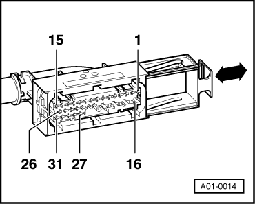
The socket designations on test box V.A.G 1598 are identical with the contact designations on control unit -J104 and the designations of the connector on the wiring harness
=> Current Flow Diagrams, Electrical Fault-finding and Fitting Locations binder
→ Contact assignment of wiring harness/control unit -J104 multiple connector.
All contacts not listed are currently not assigned and must not be connected to other components.
|
|
|---|
|
Contact
|
Wiring to component...
|
|
1
|
Rear right speed sensor -G44
|
|
2
|
Rear right speed sensor -G44
- Vehicles with FWD and ABS/EDL/TCS
- Vehicles with 4WD and ABS/EDL
|
|
3
|
Rear right speed sensor -G44
- Vehicles with FWD and ABS and ABS/EDL
|
|
3
|
Front right speed sensor -G45
- Vehicles with FWD and ABS/EDL/TCS
|
|
4
|
Front right speed sensor -G45
- Vehicles with FWD and ABS and ABS/EDL
- Vehicles with FWD and ABS/EDL/TCS with CAN bus
- Vehicles with 4WD and ABS/EDL
|
|
5
|
Front right speed sensor -G45
- Vehicles with FWD and ABS and ABS/EDL
- Vehicles with FWD and ABS/EDL/TCS without CAN bus
- Vehicles with 4WD and ABS/EDL
|
|
6
|
Front left speed sensor -G47
|
|
7
|
Front left speed sensor -G47
|
|
8
|
Rear left speed sensor -G46
|
|
9
|
Rear left speed sensor -G46
|
|
|
|---|
|
Contact
|
Wiring to component...
|
|
10
|
Electrical connection to dash panel insert (standing time signal)
- Only in vehicles with EDL. This wiring harness transmits the time signals for calculating the "standing time".
|
|
11
|
K-wire
|
|
13
|
MAD signal (masking of engine misfire monitoring)
- All vehicles with EDL without CAN bus
- On vehicles with TCS this wiring harness is also used for transmission of MMS signal (specified engine torque).
|
|
14
|
Brake light switch -F
|
|
15
|
Voltage supply from terminal 15
|
|
16
|
Earth, terminal 31 (hydraulic pump -V39)
|
|
17
|
Battery + (terminal 30)
|
|
18
|
Battery + (terminal 30)
|
|
19
|
Earth, terminal 31 (control unit -J104)
|
|
20
|
TCS lamp -K86
- Vehicles with TCS only
|
|
21
|
ABS/EDL lamp -K47
|
|
23
|
Speed sensor output, rear left
- In vehicles with navigation system
|
|
24
|
Speed sensor output, rear right.
- In vehicles with navigation system
|
|
|
|---|
|
Contact
|
Wiring to component...
|
|
27
|
MMI (engine torque - actual)
- Vehicles with TCS without CAN bus only.
|
|
28
|
GB (gearbox control signal)
- Vehicles with TCS without CAN bus only.
|
|
29
|
CAN bus low
- The following signals are transmitted via the CAN bus lines to the appropriate control units: MMI (engine torque - actual), MMS (engine torque -specified), GB (gearbox control signal) and engine speed signal.
|
|
30
|
CAN bus high
- The following signals are transmitted via the CAN bus lines to the appropriate control units: MMI (engine torque - actual), MMS (engine torque -specified), GB (gearbox control signal) and engine speed signal.
|
|
30
|
Engine speed
- Vehicles with TCS without CAN bus only.
|
|
31
|
TCS switch
- Vehicles with TCS only
|
Notes on fault table
-
◆ The socket descriptions of test box V.A.G 1598 are identical to the contact descriptions of control unit -J104 in the current flow diagram. Incorrect test procedures can cause system damage. Do not make connections between any contacts other than those listed in the test table.
=> Current Flow Diagrams, Electrical Fault-finding and Fitting Locations binder.
-
◆ The specified values refer to the readings obtained on tester V.A.G 1526 and are not necessarily applicable to other test units.
-
◆ If the readings obtained do not match the specified values, carry out the fault remedy measures in the right-hand part of the table.
=> Current Flow Diagrams, Electrical Fault-finding and Fitting Locations binder.
-
◆ If the specified values are achieved, also check wiring for loose contacts and short circuit to positive and earth. This applies especially to sporadic faults.
-
◆ Only use test lead set V.A.G 1594 for checking continuity (bridging leads).
-
◆ If the measured figures only differ slightly from the specified values, clean the sockets and plugs of the testers and test leads (with contact spray G 000 700 04) and repeat the check. Before replacing components, check wiring and connections again. This is particularly important if the specification calls for a resistance reading of less than 10 ω.
Test table
|
|
|---|
|
Switch on measuring range:
Voltage measurement (20 V =)
|
|
Test step
|
V.A.G 1598 socket
|
Testing of
|
▪ Test conditions
- Additional operations
|
Specified value
|
Action in the event of deviation from specified value
|
|
1
|
19 + 15
|
Voltage supply of control unit through terminal 15
|
▪ Ignition switched on
|
10.0 - 14.5 V
|
- Check wiring from contact 19 to earth.
Check wiring from contact 15 to terminal 15.
=> Current Flow Diagrams, Electrical Fault-finding and Fitting Locations binder
|
|
|
|---|
|
Switch on measuring range:
Voltage measurement (20 V =)
|
|
Test step
|
V.A.G 1598 socket
|
Testing of
|
▪ Test conditions
- Additional operations
|
Specified value
|
Action in the event of deviation from specified value
|
|
2
|
16 + 17
|
Voltage supply at hydraulic unit -N55 and the motor of the hydraulic pump -V39 through terminal 30 at control unit -J104
|
▪ Ignition switched on
|
10.0 - 14.5 V
|
- Check wiring from contact 16 to earth.
|
|
|
16 + 18
|
|
|
10.0 - 14.5 V
|
- Check wiring of contacts 17 and 18 via fuse (60A) to battery + (terminal 30).
=> Current Flow Diagrams, Electrical Fault-finding and Fitting Locations binder
|
|
|
|---|
|
Switch on measuring range:
Voltage measurement (20 V =)
|
|
Test step
|
V.A.G 1598 socket
|
Testing of
|
▪ Test conditions
- Additional operations
|
Specified value
|
Action in the event of deviation from specified value
|
|
3
|
19 + 14
|
Function of brake light switch-F
|
▪ Ignition switched off
|
|
- Check wiring from contact 19 to earth.
|
|
|
|
|
▪ Brake pedal not operated
Brake pedal operated
|
0.0 - 0.5 V
10.0 - 14.5 V
|
- Check wiring from terminal 14 via fuse (10A) to terminal 30.
|
|
|
|---|
|
Switch on measuring range:
Resistance measurement (2 kω)
|
|
Test step
|
V.A.G 1598 socket
|
Testing of
|
▪ Test conditions
- Additional operations
|
Specified value
|
Action in the event of deviation from specified value
|
|
4
|
4 + 5 1) 2)
3 + 5 3)
|
Resistance of speed sensor front right -G45
|
|
|
- Test electrical wiring between control unit and speed sensor for open circuit, short to earth or short to positive.
|
|
5
|
6 + 7
(all versions)
|
Resistance of speed sensor front left -G47
|
▪ Ignition switched off
|
400ω/2300ω
|
- Check plug connections.
Move wiring during check (Loose contact).
=> Current Flow Diagrams, Electrical Fault-finding and Fitting Locations binder
If the electrical wiring is OK and the specified value is not obtained, renew the relevant speed sensor.
|
1) Assignment of speed sensor contacts on vehicles with FWD and EDL.
2) Assignment of speed sensor contacts on vehicles with 4WD and EDL.
3) Assignment of speed sensor contacts on vehicles with FWD and TCS.
|
|
|---|
|
Switch on measuring range:
Resistance measurement (2 kω)
|
|
Test step
|
V.A.G 1598 socket
|
Testing of
|
▪ Test conditions
- Additional operations
|
Specified value
|
Action in the event of deviation from specified value
|
|
6
|
1 + 3 1)
1 + 2 2) 3)
|
Resistance of speed sensor rear right -G44
|
|
|
- Check electric wiring between control unit and speed sensor for open circuit and short to earth or positive.
|
|
7
|
8 + 9
(all versions)
|
Resistance of speed sensor rear left -G46
|
▪ Ignition switched off
|
400ω/2300ω
|
- Check plug connections.
Move wiring during check (Loose contact).
=> Current Flow Diagrams, Electrical Fault-finding and Fitting Locations binder
If the electrical wiring is OK and the specified value is not obtained, renew the relevant speed sensor.
|
1) Assignment of speed sensor contacts on vehicles with FWD and EDL.
2) Assignment of speed sensor contacts on vehicles with 4WD and EDL.
3) Assignment of speed sensor contacts on vehicles with FWD and TCS.
|
|
|---|
|
Functional check: ABS/EDL warning lamp-K47
|
|
Test step
|
V.A.G 1598 socket
|
Testing of
|
▪ Test conditions
- Additional operations
|
Specified value
|
Action in the event of deviation from specified value
|
|
8
|
-
|
Function of ABS/EDL warning lamp -K47.
|
▪ Fault memory was interrogated and there is no fault present in the fault memory of the control unit -J104.
▪ Ignition switched off
▪ Multi-pin connector connected to control unit -J104 and engaged.
|
|
|
|
|
|
|
|
Test step 8: Continued on next page.
|
|
|
|---|
|
Functional check: ABS/EDL warning lamp-K47
|
|
Test step
|
V.A.G 1598 socket
|
Testing of
|
▪ Test conditions
- Additional operations
|
Specified value
|
Action in the event of deviation from specified value
|
|
8
Continued:
|
-
|
Function of ABS/EDL warning lamp -K47.
|
- Switch on ignition.
|
Warning lamp -K47 is lit up for 2 seconds and then goes out again.
|
- If ABS/EDL warning lamp does not light check electrical system voltage and wiring from contact 21 of control unit -J104 to dash panel insert for short to earth.
ABS/EDL warning lamp does not extinguish after 2 seconds. After 3 seconds the symbol "Fault brake system" illuminates. Check wiring from contact 21 of control unit -J104 to dash panel insert for short to positive and open circuit.
=> Current Flow Diagrams, Electrical Fault-finding and Fitting Locations binder
|
|
|
|
|
|
|
- If the voltage of the vehicle electrical system is OK and wiring from contact 21 of control unit -J104 to dash panel insert is intact => fault in dash panel insert; LEDs or bulbs defective
|
|
|
|---|
|
Functional check: Red brake fault symbol
|
|
Test step
|
V.A.G 1598 socket
|
Testing of
|
▪ Test conditions
- Additional operations
|
Specified value
|
Action in the event of deviation from specified value
|
|
9
|
-
|
Function of red symbol "Fault brake system"
|
▪ Brake fluid level OK
|
|
|
|
|
|
|
|
Test step 9: Continued on next page.
|
|
Functional check: Red brake fault symbol
|
|
Test step
|
V.A.G 1598/20 sockets
|
Testing of
|
▪ Test conditions
- Additional operations
|
Specified value
|
Action in the event of deviation from specified value
|
|
9
Continued:
|
|
Function of red symbol "Fault brake system"
|
- Connect V.A.G 1551, select address word 03
On vehicles with automatic gearbox and high-line dash panel insert, press brake pedal and engage a gear.
|
ABS warning lamp and red brake fault symbol should light up. On vehicles with TCS traction control, TCS warning lamp will also light up if it is working properly.
|
- Fault in dash panel insert
|
|
|
|---|
|
Functional check: Warning lamp for TCS -K86 is only present with TCS.
|
|
Test step
|
V.A.G 1598 socket
|
Testing of
|
▪ Test conditions
- Additional operations
|
Specified value
|
Action in the event of deviation from specified value
|
|
10
|
-
|
Function of TCS warning lamp -K86
|
▪ Fault memory was interrogated and there is no fault present in the fault memory of the control unit -J104.
▪ Ignition switched off
▪ Multi-pin connector connected to control unit -J104 and engaged.
|
|
|
|
|
|
|
|
Test step 10: Continued on next page.
|
|
|
|---|
|
Functional check: Warning lamp for TCS -K86 is only present with TCS.
|
|
Test step
|
V.A.G 1598 socket
|
Testing of
|
▪ Test conditions
- Additional operations
|
Specified value
|
Action in the event of deviation from specified value
|
|
10
Continued:
|
-
|
Function of TCS warning lamp -K86
|
- Switch on ignition.
|
Warning lamp -K86 should light up for 2 seconds and then extinguish.
|
- If the TCS warning lamp does not light up, check voltage of electrical system and test wiring from contact 20 of control unit -J104 to dash panel insert for open circuit and short to positive.
If the TCS warning lamp illuminates continuously, check the wiring from contact 20 of control unit -J104 to the dash panel insert for a short to earth.
=> Current Flow Diagrams, Electrical Fault-finding and Fitting Locations binder
|
|
|
|
|
|
|
- If the voltage of the vehicle electrical system is OK and wiring from contact 20 of control unit -J104 to dash panel insert is intact => fault in dash panel insert; LEDs or bulbs defective
|
|
|
|---|
|
Functional check: TCS switch, select measuring range on V.A.G 1526: 20 V =
|
|
Test step
|
V.A.G 1598 socket
|
Testing of
|
▪ Test conditions
- Additional operations
|
Specified value
|
Action in the event of deviation from specified value
|
|
11
|
-
|
Function of TCS switch
|
▪ Ignition switched off
▪ Function of TCS warning lamp -K86 checked in test step 10.
▪ Multi-pin connector connected to control unit -J104 and engaged.
Switch on ignition.
|
|
|
|
|
|
|
- Operate TCS switch.
|
TCS warning lamp -K86 illuminates.
|
- Switch off the ignition.
Release multiple connector from control unit -J104 and detach.
|
|
|
|
|
- Press TCS switch again.
|
TCS warning lamp -K86 goes out.
|
- Connect test box V.A.G 1598 with adapter cable V.A.G 1598/27.
|
|
|
|
|
|
Test step 11: Continued on next page.
|
|
|
|---|
|
Functional check: TCS switch, select measuring range on V.A.G 1526: 20 V =
|
|
Test step
|
V.A.G 1598 socket
|
Testing of
|
▪ Test conditions
- Additional operations
|
Specified value
|
Action in the event of deviation from specified value
|
|
11
|
19 + 31
|
Function of TCS switch
|
▪ Ignition switched on
|
|
|
|
Continued:
|
|
|
- TCS switch not pressed
|
0.0 - 0.5 V
|
|
|
|
|
|
- TCS switch pressed
|
10.0 - 14.5 V
|
- Check wiring from contact 19 to earth.
Check wiring from contact 31 to TCS switch, contact 6.
Check voltage supply from contact 5 of TCS switch to terminal 15.
=> Current Flow Diagrams, Electrical Fault-finding and Fitting Locations binder
If no fault has been found in the previous test steps, renew TCS switch.
|
|