audi Workshop Repair Guides

Audi Workshop Service and Repair Manuals

System Description > < Function of CAN-Bus
Running Gear Self-diagnosis for ABS, ESP
CAN bus
Test the CAN bus system

It was advised in the fault table to check the bus:

  • ‒ By referring to the appropriate current flow diagram, check how many control units are connected to the CAN bus.
  • ‒ Check that the multi-pin connectors on the control units are properly seated.
  • ‒ Connect fault reader V.A.G 1551 or V.A.G 1552 and press key 0 twice to select the function "Automatic test sequence"
  • Ensure that there is no function fault in any of the connected control units before examining the bus lines.

A function fault refers to a fault that does not directly affect the bus system but affects the functionality of a system in some other way. For example, this may be a defective sensor. The result is that the sensor signal cannot be prepared for transferring on the bus system. A functional fault of this nature has a direct effect on the bus system. Communication with the other control units that require the sensor signal concerned is affected.

Is there a function fault?

  • Repair it first.
  • ‒ Make a note of the faults and erase fault memory of all control units .
  • ‒ Press keys 0 and 6 for the "End output" function and press the Q key to confirm entry.
  • ‒ End output of fault reader with the function "End output" => Page 01-14.
  • ‒ Rectify the faults as described in the fault table in the relevant Workshop Manual.

All function faults have been rectified.

  • ‒ If the communication between the control units is still interrupted the bus lines must be examined.

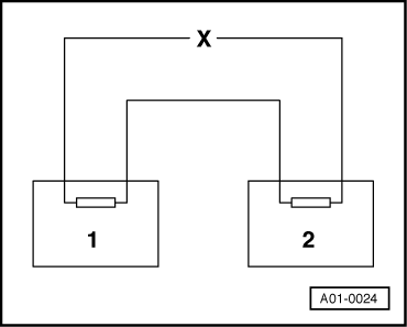
There are two different cases when looking for faults in the bus lines:

  • ◆ Two control units communicate via a "Two-line bus system".
  • ◆ Three or more control units communicate via a "Two-line bus system".

The communication between two control units is carried out via a "Two-line bus system".

 
A01-0024
  • ‒ Switch ignition off.
  • ‒ → Disconnect the two control units.
  • ‒ Investigate whether one of the bus lines has an open circuit.

=> Current Flow Diagrams, Electrical Fault-finding and Fitting Locations binder

 
A01-0025
  • ‒ → Check whether there is a short circuit between the bus lines.

=> Current Flow Diagrams, Electrical Fault-finding and Fitting Locations binder

 
A01-0026
  • ‒ → Check whether there is a short to positive or earth in one of the bus lines.

No fault can be detected at the bus lines.

  • ‒ As a test, replace the control unit which can be exchanged with the least effort in terms of time and cost.
  • ‒ If the communication between the control units via the bus is still faulty exchange the second control unit.

The communication between three or more control units is carried out over a "two-line bus system".

  • ‒ Evaluate the faults stored in the control units.

Example 1:

The faults stored in the fault memories indicate that the control unit 1 does not communicate with control units 2 and 3.

 
A01-0027

Control unit

Faults stored in fault memory

1

- Missing message from control unit 2
- Missing message from control unit 3

2

- Missing message from control unit 1

3

- Missing message from control unit 1

  • ‒ Switch ignition off.
  • ‒ Disconnect the control units connected to each other via the bus lines and investigate whether there is a short circuit between the bus lines.

=> Current Flow Diagrams, Electrical Fault-finding and Fitting Locations binder

  • ‒ If no fault can be detected in the bus lines, replace control unit 1.

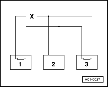
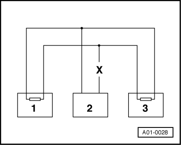
Example 2:

The faults stored in the fault memories indicate that the control unit 2 does not communicate with control units 1 and 3.

 
A01-0028

Control unit

Faults stored in fault memory

1

- Missing message from control unit 2

2

- Missing message from control unit 1
- Missing message from control unit 3

3

- Missing message from control unit 2

  • ‒ Switch ignition off.
  • ‒ Disconnect the control units connected to each other via the bus lines and investigate whether there is a short circuit between the bus lines.

=> Current Flow Diagrams, Electrical Fault-finding and Fitting Locations binder

  • ‒ If no fault can be detected in the bus lines, replace control unit 2.

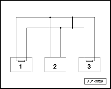
Example 3:

The faults stored in the fault memories indicate that sending or receiving is not possible in any of the control units.

 
A01-0029

Control unit

Faults stored in fault memory

1

- Hardware defective

2

- Hardware defective

3

- Hardware defective

  • ‒ Switch ignition off.
  • ‒ → Disconnect the control units that are linked by the bus wires and check for a short circuit between the bus wires

=> Current Flow Diagrams, Electrical Fault-finding and Fitting Locations binder

 
A01-0030
  • ‒ → Check the bus wires for short to positive and short to earth.
  • If the reason for "Hardware defective" cannot be established in the bus wires, check whether one of the control units is responsible for the fault.
  • All the control units that communicate via the CAN data bus are still disconnected. The ignition is switched off.
    • ‒ Connect one of the control units.
    • ‒ Connect fault reader V.A.G 1551 or V.A.G 1552. Switch the ignition on and erase the fault memory of the control unit that has just been connected Terminate fault readout by selecting function 06 "End output".
    • ‒ Switch the ignition off and then on again.
    • ‒ Leave the ignition switched on for 10 seconds. Then interrogate the fault memory of the control unit that has just been connected, using the fault reader.
    • ‒ If the "Hardware defective" is indicated, replace the control unit that has just been connected.
    • ‒ If the "Hardware defective" fault is not indicated, connect the next control unit and repeat the above procedure.

System Description > < Function of CAN-Bus