| Checking “two-wire bus system” |
| –
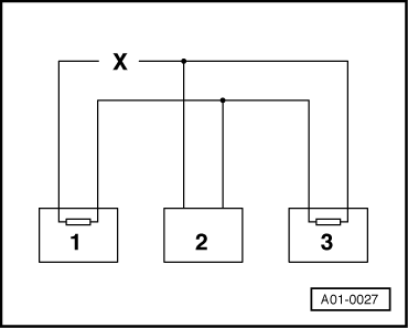
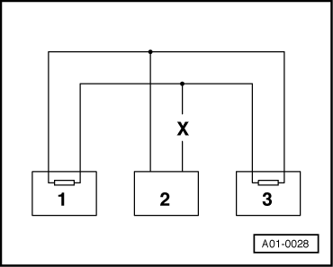
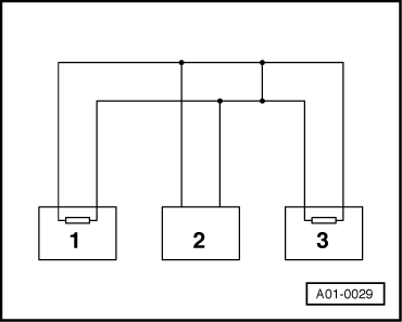
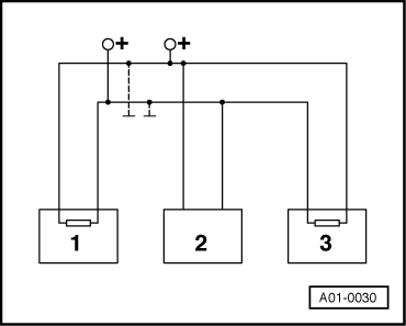
| Use the corresponding current flow diagram to determine how many control units communicate with one another by way of the bus. |
| –
| Connect vehicle diagnostic, testing and information system -VAS 5051B- → Chapter and select function “00 - Automatic test sequence”. When doing this, the ignition must be switched on. |
| –
| Before examining the bus wires, make sure that there is no malfunction in any of the control units linked to the bus. Malfunctions interfere with communication with other control units. |

Note | The term malfunction refers to a fault which does not directly affect the bus system but in some way disrupts the operating sequence of a system. This may be a defective sensor for example. The consequence is that the sensor signal can no longer be conditioned for the bus system data transfer. Such malfunctions have an indirect effect on the bus system. Communication with the other control units requiring the relevant sensor signal is impaired. |
| Has a malfunction occurred? |
| –
| This must first be repaired. |
| –
| Print out fault list and erase fault memories of all control units. Refer to “Interrogating fault memory” and “Erasing fault memory” of corresponding control unit. |
| –
| Touch function “06 - End output”. |
| –
| Eliminate the malfunctions on the basis of the fault tables in the relevant workshop manuals. |
| All malfunctions eliminated? |
| –
| If there are still problems with control unit communication, the bus wires must be examined. |
|
|
|