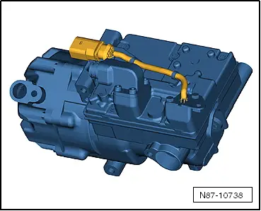
| Electrically driven air conditioner compressor for vehicles with a high-voltage system |

WARNING | Safety hazard: the engine can start unexpectedly. |
| Before carrying out general work on a vehicle with high-voltage electrical system, switch off the ignition and remove the ignition key from the vehicle. |
|
WARNING | Working on vehicles with high-voltage wiring: |
| l
| Do not support yourself or tools on high-voltage wiring or associated components --> this can damage the insulation. |
| l
| High-voltage wiring must not be excessively bent or kinked --> this can damage the insulation. |
| l
| The round high-voltage connectors are colour-coded with an external coloured ring and are provided with mechanical coding or guide lugs. It is important to observe this coding when joining up the round high-voltage connectors, otherwise the connectors can be damaged. |
|
DANGER! | Risk of fatal injury if high-voltage components are damaged. |
| Observe the following when working in the vicinity of high-voltage components or wiring: |
| t
| It is not permitted to use cutting or forming tools, other sharp-edged tools or heat sources such as welding, brazing, soldering, hot air or thermal bonding equipment. |
| t
| Before starting work, visually inspect the high-voltage components in the areas involved. |
| t
| Before working in the engine compartment, visually inspect the power electronics -JX1-, electric drive motor -V141-, air conditioner compressor -V470- and high-voltage wiring. |
| t
| Before working on the vehicle underbody, visually inspect the high-voltage wiring and covers. |
| t
| Before working on the rear section of the vehicle, visually inspect the high-voltage wiring and the electro-box with the maintenance connector for high-voltage system - TW -. |
| t
| Visually inspect all potential equalisation lines. |
| Check the following when making the visual inspection: |
| t
| There must be no external damage on any component. |
| t
| The insulation of the high-voltage wiring and potential equalisation lines must not be damaged. |
| t
| There must be no unusual deformation of the high-voltage wiring. |
| t
| All high-voltage components must be identified by a red warning sticker. |
|
| If work is necessary in the vicinity of high-voltage system components, perform a visual inspection of the high-voltage components and wiring to check for damage → Chapter and note → Electrical system; Rep. gr.93. |
| De-energising high-voltage system |
DANGER! | Voltage can cause fatal injury. |
| Danger of severe or fatal injuries from electric shock. |
| t
| For reasons of safety, persons with life-preserving or other electronic medical devices in or on their body must not perform any work on the high-voltage system. Such medical devices include internal analgesic pumps, implanted defibrillators, pacemakers, insulin pumps and hearing aids. |
| t
| The high-voltage system may only be de-energised by a suitably qualified person (Audi high-voltage technician). |
| t
| It must be definitely confirmed that the high-voltage system is de-energised. The system may only be de-energised using the vehicle diagnostic tester via „Guided Fault Finding“. |
| t
| The qualified person (Audi high-voltage technician) confirms that the system is de-energised and uses the locking cap -T40262- to ensure that the system cannot be re-energised. The ignition key and the maintenance connector for high-voltage system - TW - should then be stored in a safe place by the qualified person. |
| t
| The qualified person (Audi high-voltage technician) marks the vehicle by attaching the appropriate warning signs. |
|

Note | t
| De-energising high-voltage system: |
| t
| Connect vehicle diagnostic tester |
| t
| Select Guided Fault Finding mode |
| t
| Using the Go to key, select the following menu items in succession |
| t
| Function/component selection |
| t
| Self-diagnosis compatible systems |
| t
| 8C - Hybrid battery management -J840 |
| t
| 8C - Hybrid battery management, functions |
| t
| 51 - De-energise high-voltage system (Rep. gr. 93) |
| Re-energising high-voltage system |
DANGER! | Voltage can cause fatal injury. |
| Danger of severe or fatal injuries from electric shock. |
| t
| For reasons of safety, persons with life-preserving or other electronic medical devices in or on their body must not perform any work on the high-voltage system. Such medical devices include internal analgesic pumps, implanted defibrillators, pacemakers, insulin pumps and hearing aids. |
| t
| The high-voltage system may only be re-energised by a suitably qualified person (Audi high-voltage technician). |
| t
| The system may only be re-energised using the vehicle diagnostic tester via „Guided Fault Finding“. |
| t
| The vehicle is then made ready for operation again by the qualified person (Audi high-voltage technician). |
| t
| The qualified person (Audi high-voltage technician) marks the vehicle by attaching the appropriate warning signs. |
|
Note | t
| Re-energise high-voltage system: |
| t
| Connect vehicle diagnostic tester |
| t
| Select Guided Fault Finding mode |
| t
| Using the Go to key, select the following menu items in succession |
| t
| Function/component selection |
| t
| Self-diagnosis compatible systems |
| t
| 8C - Hybrid battery management -J840 |
| t
| 8C - Hybrid battery management, functions |
| t
| 51 - Re-energise high-voltage system (Rep. gr. 93) |
DANGER! | When working on a vehicle with the ignition switched on or while the drive system is active, the engine can start unexpectedly and exhaust fumes can cause a health hazard in closed rooms. Moving parts can trap or draw in parts of the body and/or clothing (safety hazard). |
| Before switching on the ignition, perform the following steps: |
| t
| Move selector lever to position P |
| t
| Connect battery charger (e.g. -VAS 5095A-) to jump-start connections of 12 V electrical system |
|
| –
| For test and measurement work that requires the vehicle's drive system to be active or the ignition to be switched on, move the selector lever to position „P“, activate the parking brake and arrange the tools needed so that they cannot come into contact with moving components of the engine and so that they cannot even come near to components that turn when the engine is running. |
|
|
|