
A4 Mk2
 Note
Note
|
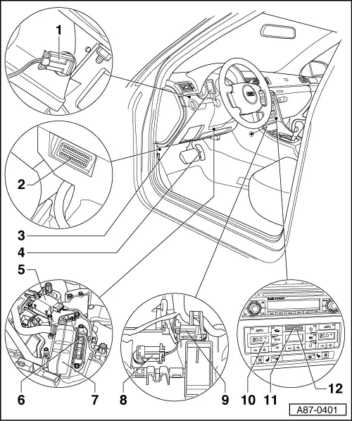
| 1 - | Left vent temperature sender -G150- → Anchor1) |
| q | Removing and installing → Chapter |
| 2 - | Diagnostic socket |
| q | Performing air conditioner self-diagnosis → Chapter |
| 3 - | Dash panel insert |
| q | With control unit in dash panel insert -J285- and ambient temperature indicator -G106- → Anchor2) |
| q | The ambient temperature output by the operating and display unit, Climatronic control unit -J255- is only displayed for example on vehicles with automatic gearbox if a gear is engaged |
| q | Checking measured values of temperature sensors if temperature reading is incorrect → Chapter |
| q | Measured value of ambient temperature sensor -G17- is evaluated by control unit in dash panel insert -J285- and transmitted by way of convenience data bus system to operating and display unit, Climatronic control unit -J255- → "Guided fault-finding" function of vehicle diagnostic, testing and information system VAS 5051 and → Electrical system; Rep. Gr.01 |
| 4 - | Accelerator mechanism |
| q | Kick-down deactivation of the air conditioning system compressor regulating valve -N280- is effected by way of the relevant engine control unit → "Guided fault-finding" function of vehicle diagnostic, testing and information system VAS 5051, → Injection and ignition system; Rep. Gr.01 and → Diesel direct injection and glow plug system; Rep. Gr.01 |
| 5 - | Left temperature flap control motor -V158- → Anchor2) |
| q | With left temperature flap control motor potentiometer -G220- → Anchor1) |
| q | Lever colour code: Red (yellow for right-hand drive vehicles) |
| q | Removing and installing → Chapter |
| 6 - | Auxiliary heater element -Z35- → Anchor2) |
| q | Only intended for vehicles with diesel engine not fitted with a fuel-driven supplementary heater → Chapter |
| q | Removing and installing → Chapter |
| q | Checking operation → Chapter |
| 7 - | Heating system heat exchanger |
| q | Removing and installing → Chapter |
| 8 - | Left footwell vent temperature sender -G261- → Anchor1) |
| q | Removing and installing → Chapter |
| 9 - | Right footwell vent temperature sender -G262- → Anchor1) |
| q | Removing and installing → Chapter |
| 10 - | Operating and display unit, Climatronic control unit -J255- |
| q | Different versions, assignment → Parts List |
| q | Removing and installing → Chapter and → Chapter |
| q | The temperature sensor blower -V42- and the dash panel temperature sensor -G56- are integrated into the operating and display unit, Climatronic control unit -J255- |
| q | Heed additional notes → Chapter |
| q | Checking code and encoding → Chapter |
| q | Display zones and buttons are illuminated by LEDs which cannot be replaced |
| q | Depending on the date of issue, the operating and display unit, Climatronic control unit -J255- may also be referred to as air conditioning system/Climatronic operating and display unit -E87- in various workshop publications (e.g. in current flow diagrams for vehicles up to Model Year 2004). |
| 11 - | Temperature sensor blower -V42- → Anchor2) |
| q | Installed in operating and display unit, Climatronic control unit -J255-, cannot be replaced separately |
| 12 - | Dash panel temperature sensor -G56- |
| q | Installed in operating and display unit, Climatronic control unit -J255-, cannot be replaced separately |
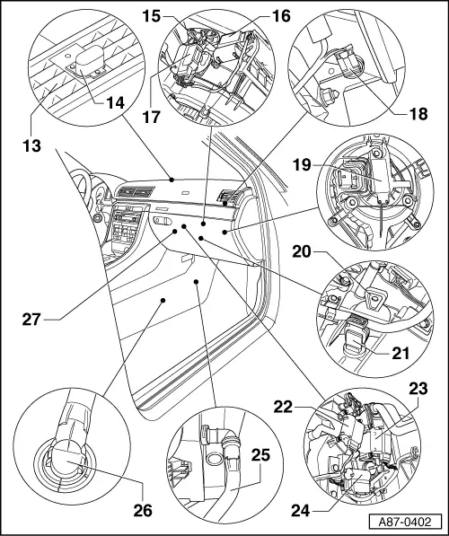
| 13 - | Defroster vent |
| q | For windscreen |
| q | Removing and installing → General body repairs, interior; Rep. Gr.70 |
| 14 - | Sunlight penetration photosensor -G107- → Anchor1) |
| q | Removing and installing → Chapter |
| q | Different versions for vehicles up to chassis number “399999” in Model Year 2005 (Saloon and Avant) or “012912” in Model Year 2005 (Cabrio) and as of chassis number “400000” in Model Year 2005 (Saloon and Avant) or “012913” in Model Year 2005 (Cabrio) → Parts catalogue; heed the exact assignment → Chapter and → Parts catalogue |
| 15 - | Fresh-air intake duct temperature sensor -G89- → Anchor1) |
| q | Checking → Chapter |
| q | Removing and installing → Chapter |
| 16 - | Air recirculation flap control motor -V113- → Anchor2) |
| q | With air recirculation flap control motor potentiometer -G143- |
| q | Lever colour code: Blue (light blue with additional lugs for actuation of fresh-air flap on right-hand drive vehicles) |
| q | Removing and installing → Chapter |
| q | On right-hand drive vehicles also actuates fresh-air flaps (no air flow flap control motor -V71- fitted) |
| 17 - | Air flow flap control motor -V71- → Anchor2) |
| q | On left-hand drive vehicles, this motor actuates fresh-air and air flow flaps |
| q | Only fitted on left-hand drive vehicles |
| q | Right-hand drive vehicles have no air flow flap; the fresh-air flaps are actuated by the air recirculation flap control motor -V113- (no air flow control) |
| q | With air flow flap control motor potentiometer -G113- → Anchor1) |
| q | Cam plate colour code: Light blue |
| q | Removing and installing → Chapter |
| 18 - | Right vent temperature sender -G151- → Anchor1) |
| q | Removing and installing → Chapter |
| 19 - | Fresh air blower control unit -J126- and fresh air blower -V2- → Anchor2) |
| q | Removing and installing → Chapter |
| q | The fresh air blower -V2- contains the fresh air blower control unit -J126- as an integral component which cannot be replaced separately. |
| 20 - | Air duct connection for glove box cooling |
| q | Vehicles without glove box cooling are fitted with a plug (Fig.). |
| q | For glove box cooling components, refer to → General body repairs, interior; Rep. Gr.68 |
| q | Removing and installing → Chapter |
| 21 - | Evaporator outflow temperature sender -G263- → Anchor1) |
| q | Removing and installing → Chapter |
Note| The evaporator may ice up if the evaporator outflow temperature sender -G263- is not properly installed in the air conditioner unit air flow. |
| 22 - | Central flap control motor -V70- → Anchor2) |
| q | With central flap control motor potentiometer -G112- → Anchor1) |
| q | Cam plate colour code: White (black for right-hand drive vehicles) |
| q | Removing and installing → Chapter |
| 23 - | Defroster flap control motor -V107- → Anchor2) |
| q | With defroster flap control motor potentiometer -G135- → Anchor1) |
| q | Lever colour code: Dark green (light green for right-hand drive vehicles) |
| q | Removing and installing → Chapter |
| 24 - | Right temperature flap control motor -V159- → Anchor2) |
| q | With right temperature flap control motor potentiometer -G221- → Anchor1) |
| q | Lever colour code: Violet (brown for right-hand drive vehicles) |
| q | Removing and installing → Chapter |
| 25 - | Condensate drain |
| q | Checking → Chapter |
| q | Removing and installing → Chapter |
Note| Incomplete condensate drainage may result in an odour nuisance. |
| 26 - | Condensate drain valve |
| q | Checking → Chapter |
| q | Removing and installing → Chapter |
| 27 - | Air conditioner unit with evaporator |
| q | Removing and installing → Chapter |
| q | Dismantling and assembling → Chapter |
| q | Cleaning evaporator of air conditioner with ultrasonic air conditioner cleaning unit -VAS 6189- → Chapter |
| q | Always drain refrigerant circuit before removing; vehicle must be taken to a specialist air conditioner workshop |