| –
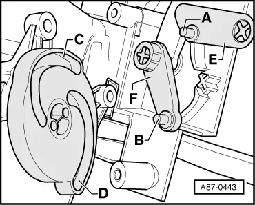
| Insert lug -A- in groove -C- and lug -B- in groove -D- of cam plate (lugs -A- and -B- as well as grooves -C- and -D- have different dimensions). |

Note | On insertion, make sure that actuating arms -E- and -F- are correctly positioned on the corresponding pivot pins. |
| Re-install all parts removed in reverse order, paying attention to the following: |
| –
| Lay wiring harness such that it cannot come into contact with moving components (e.g. control motor lever). |
Note | Operation of the control motor can be checked as follows for example: Connect the two contacts “5” and “6” in the control motor connector to a 12V DC source. The control motor moves as far as the stop in one direction. Interchanging positive and negative reverses direction. Use adapter cable for this purpose → Chapter. |
|
|
|
